86Duino Zero Hardware Introduction
Introduction
86Duino Zero is a development board with a micro controller based on the x86 architecture. It includes a 32 bit x86 CPU Vortex86EX and is also compatible with Arduino sketches. The Zero is an entry level board in the 86Duino series and provides the same output interface as the Arduino UNO and Leonardo. The board also includes Ethernet, USB 2.0 and microSD card support which is not available out-of-the-box for Arduino UNO and Leonardo. The user does not need to add any additional I/O board for Ethernet, USB, or microSD. Moreover, the Zero can execute commands at speeds up to ten times faster than the standard Arduino. The Zero can meet the higher demands required for computational applications. Learning to use the 86Duino Zero is not difficult due to the simplistic interface and compatibility with Arduino and its countless resources. Regardless of educational back ground, if you have some basic computer knowledge or simply wish to start learning about microcomputer or embedded systems, this is perfect for you. You can now design and create an interactive project of your own with the 86Duino Zero.
Hardware Spec
- CPU : X86 structure with 32 bit processor Vortex86EX, clock speed with 300MHz( can be raise to 500MHz by using Sysimage tool)
- RAM : DDR3 SDRAM with 128MB/1GB
- Flash Memory : Build 8MB, pre-install BIOS and 86Duion firmware system
- 10M/100Mbps Ethernet x 1
- USB port x 1
- MicroSD slot x 1
- Internal power input by USB device connector ( 5V input, Type B micro-USB female, can also be connector for installing programs)
- External power input 7v-12v x 1
- GPIO connector x 17
- TTL port (UART) x 1
- Encoder connector x 1
- A/D input connector x 6
- PWM output connector x 7
- SPI connector x 1
- 12C connector x 1
- 2 pin output 5v connector, 2 pin output 3.3v connector
- Length: 76.98mm, Width: 53.34mm
- Weight: 41g
I/O connectors
Dimension
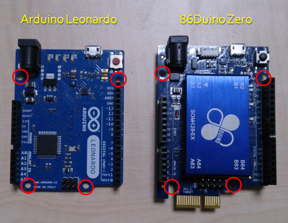
86Duino Zero is similar in size to the Arduino Leonardo, see below (Download here: Dimension)
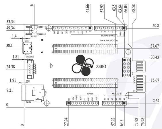
As you can see, the pins are located in the same location as the Arduino Leonardo.
Connectors
86Duino Zero Pin-Out Diagram (Click to enlarge):
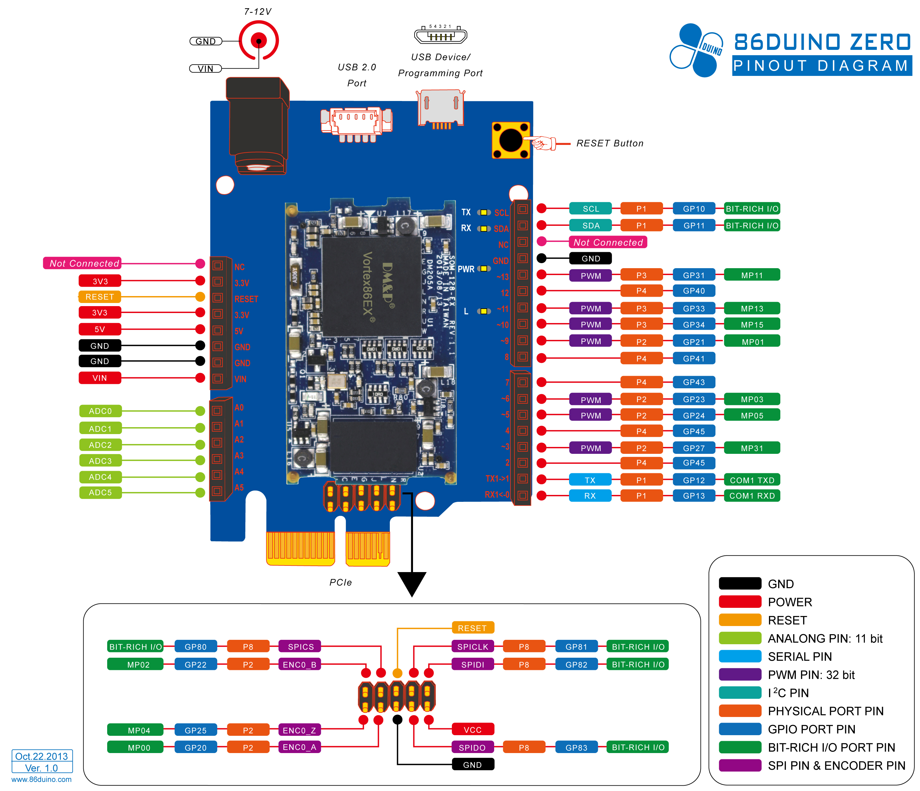
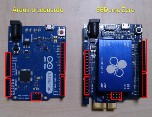
As you can see, the 86Duino Zero connectors and Arduino Leonard are extremely similar. This means the Zero is compatible with the expansion boards used in conjunction with the Arduino Uno and Leonardo (For example Arduino Wi-Fi Shield).
I/O Connector function introduce
A. Power source
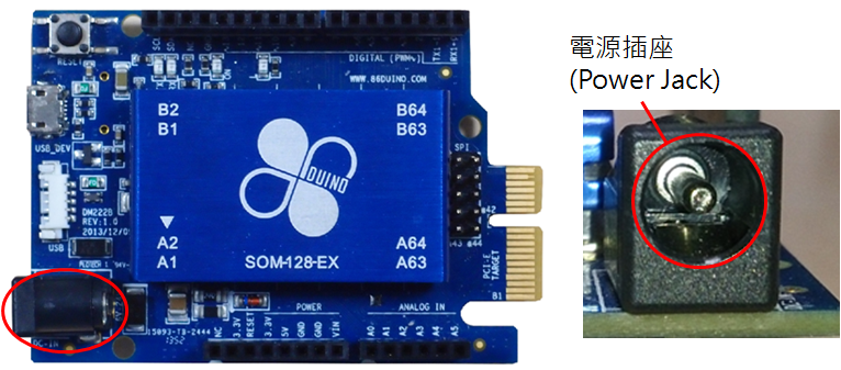
The 86Duino Zero has two power input connectors. One is for an external power input connector with black power jack. Please see left picture below. The input power range is from 7v to 12v.
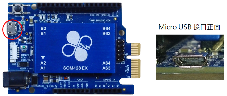
Another power input connector(micro-USB) is for installing programs but can also supply power (5v) to device.
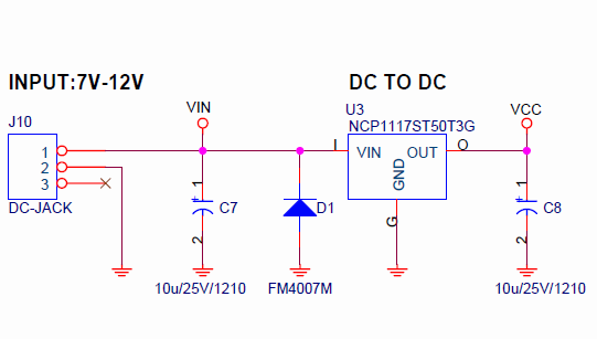
User can use either of the above connectors for power input. When using an external power source, the power will go through a step down chip so it can create a very stable 5v for all the components on the board, see below picture:
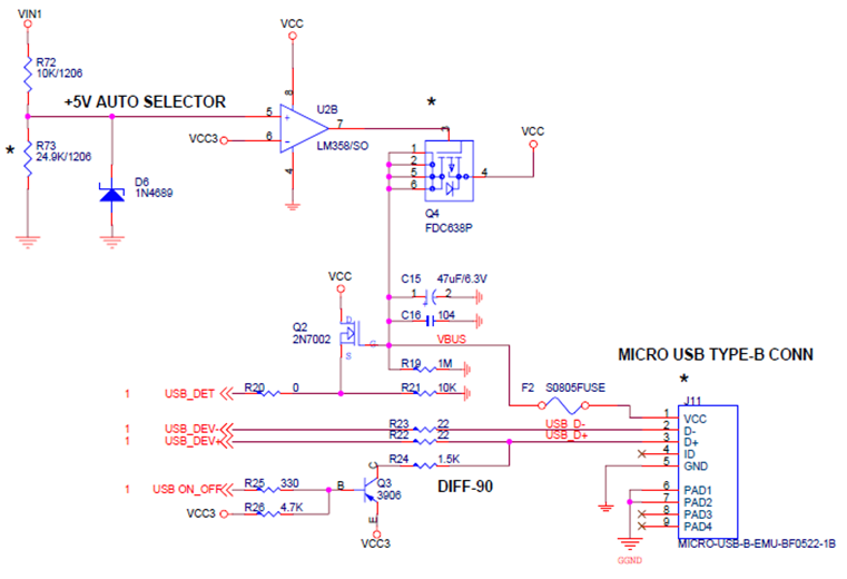
When connecting via micro-USB, the 5v power will use the bypass method to provide power for the components on the board. The external power connector and micro-USB connector can be connected at the same time as the Zero will automatically select the most stable current, as shown below :
Connect power by external power adapter
If you are using the black power connector on the board, you will need a power adapter with an output from 7v-12v with 2.1mm connector. Plug in the black power connector on the board, as shown below :
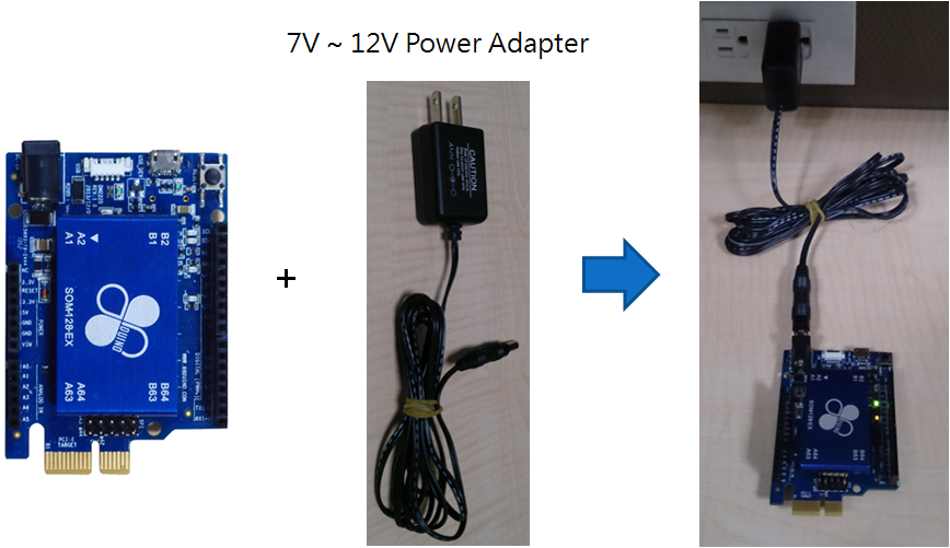
We suggest using a power adapter with an output of at least 0.5A.
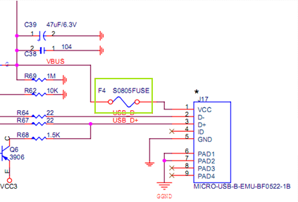
Power from micro-USB connector
You can use the micro-USB connector with USB power supply of 5v for the Zero. In order to prevent damage on the USB port by improper usage, we have built in a fuse with 1A for protection.
You will need to get a micro-USB to Type A USB cable (For example: most standard non-Apple smart phone cable; 86Duino Zero Cable Set). Use this cable to connect the Zero with a PC or Laptop’s USB port to get power.
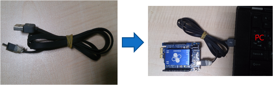
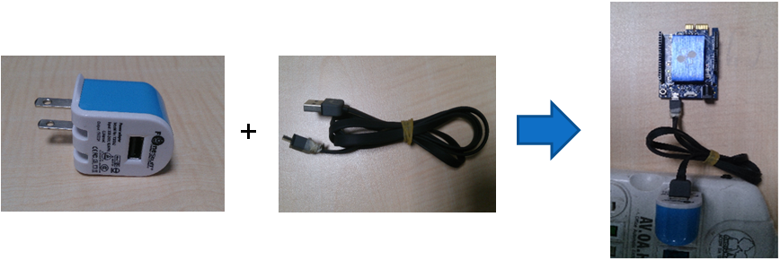
Providing power to the Zero can also be done with a smart phone power adapter or power bank that supplies microUSB output.
Please note, the 86Duino Zero requires a minimum of 370mA of power to keep it operating normally. The average PC or Laptop USB 2.0 port can provide a maximum of 500mA power which is more than enough for Zero. However, if the Zero is connected to other devices via USB such as a USB mouse (or a USB device connected to 5v and 3.3v output) the device will consume additional power and the total power may consume more than 500mA. If changed to a USB 3.0 port, 900mA can be provided for the Zero.
Note: Some older PCs or Laptops with outdated designs at the USB port will provide less than 500mA. If/When using these USB port for a power source for 86Duino Zero, please understand that there may be some unexpected results (e.g. unable to boot or install software). In this case, we would suggest using a different source for power and data.
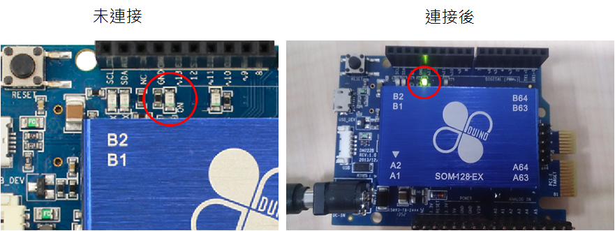
Power LED indicator
When the 86Duino is connect to power correctly, the power LED indicator will light up as shown.
Power output connector
86Duino Zero has a few pins for power output, including three different voltages: 3.3V, 5V and VIN.
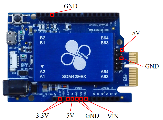
3.3V, 5V output pin can be used as a voltage source circuit for electronic experiments. The highest output currents are 400mA for the 3.3v pin and 600mA for 5V pin. The output for VIN and black power connector used with an external power input are shared. In other words, the VIN pin will provide a larger current for external devices or power source.
Please note: if your test circuit needs to consume more than 600mA (For example DC Motor power circuit), you should use VIN output pin to provide the power. Try to avoid using 5V or 3.3V output pin. Furthermore, due to the VIN output being higher than 5V, you should not connect it with other I/O connector in order to avoid a shortage.
B. Micro SD slot
86Duino Zero can support up to 32GB SDHC microSD card (not supporting SDXC). Please note, If you want to install Windows or Linux in the microSD card, the speed on the read and write for the Micro SD is going to affect the speed for the boot up time for the Operating System. We suggest a class 10 microSD card.
We provide a tool call SysImage that you can use to make a 86Duino system bootable. There are some advantages to having 86Duino system execution from the microSD card. Please see a reference this document.
Boot up order
When booting up the Zero, BIOS will look in three locations for a bootable drive: Built-in Flash memory, microSD card, and USB drive. The order will be: microSD, USB, and finally built-in flash. The Flash memory comes with the 86Duino system installed by default. If the user does not plug in a bootable storage device, the Zero will boot up from Flash memory!
Note: Caution. If you plug in a bootable microSD card or USB thumb drive with no Operating System (e.g. Windows or Linux), the Zero will fail to boot.
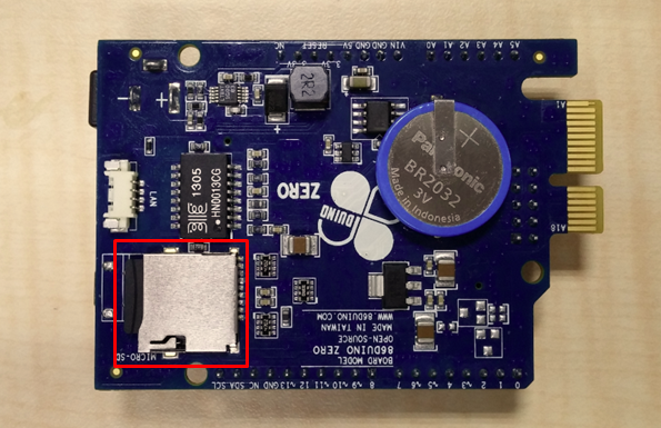
Micro SD card insert direction
The microSD slot is located on the bottom side of the Zero board as shown in the picture below:
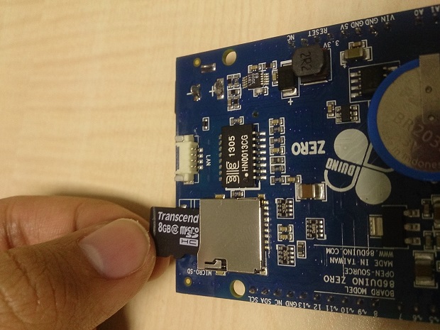
The location of the microSD slot is situated further in than a standard Arduino SD extend card or a development board for other embedded to avoid impact with other objects (For example: another robot ) when they are moving. This design also helps prevent accidental side impact should the board be dropped.
C. GPIO connector (Digit input/output pin)
86duino Zero provides 17 GPIO pin connectors. You can implement digitalWrite functions at these pins send out HIGH or LOW. Or call digitaRead function to read the pins input status.
Every GPIO pin contains either an input or output direction. You can use pinMode function to set the direction. When the GPIO is set as output, output HIGH is 3.3V and LOW is 0V. The highest output for every pin is 16mA. When GPIO is set up as input, the input current can be 0 to 5V.
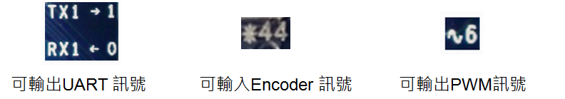
86Duino Zero and Arduino are alike in another sense in that there are different GPIO pins. For example: if the pin number shows a ~ symbol, this indicates it can output PWM signal. If showing an RX or TX symbol, it can output UART serials signals. And if it shows EA, EB and EZ symbol, this indicates that it can input Encoder signal.
If you need more information regarding the GPIO, Please see this document.
D. LED indicator
The LED indicator is the most convenient way to check status during development. There are a total of 4 LED indicators on the 86duino Zero board: (1) Power LED, if the unit is ON, the light will shine green. (2) TX LED, when the Zero sends out data from a USB Device connector to PC, it will start blinking. (3)RX LED, when the Zero receives data from PC via USB Device connector, it will blink. (4) The symbol is L for this LED, and is controlled by Pin13, on or off.
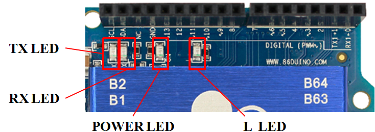
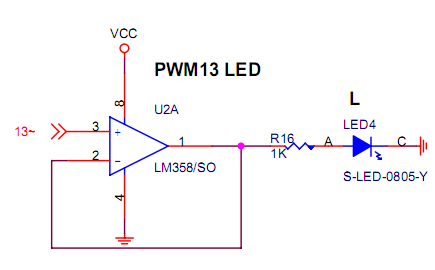
When Pin 13 output is HIGH, the L indicator will light up orange, when output is LOW, the L indicator will go off.
E. RESET
86Duino Zero board provides a RESET button and a RESET pin as shown below:
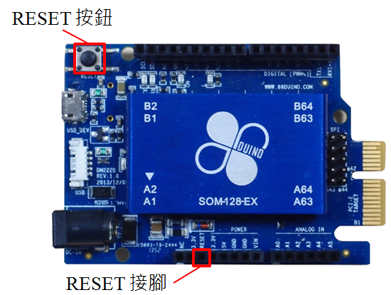
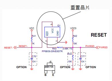
RESET Pin is connected to a reset chip on the CPU module. Creates a low current to the RESET pin which initializes reboot.
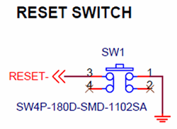
RESET button is essentially connected to RESET Pin. If you press the RESET button, the unit will also reboot.
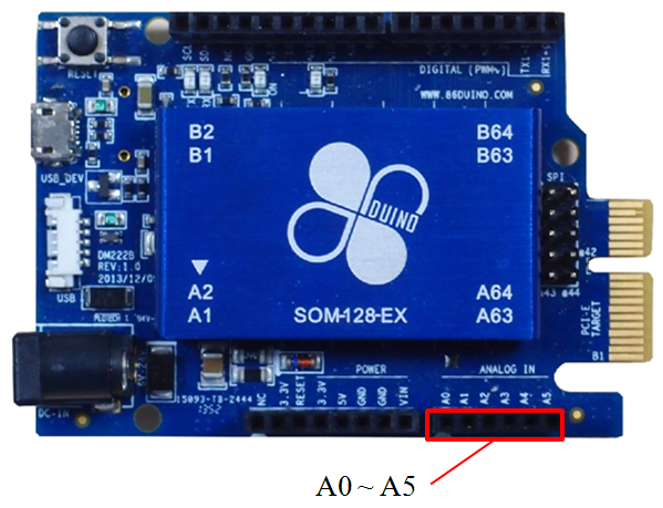
F. A/D pin (Analog input connector)
86Duino Zero provides 6 analog input, from AD0-AD5, and is located on the picture below:
Every channel has the highest 11 bits resolution. You can call analogRead function to read A/D channel’s voltage value. In order to be compatible with the Arduino, the default resolution for the A/D from analogRead function is 10 bits. However, using the analogReadResolution function, the resolution can be adjusted to highest 11 bits.
Please note: the range for input current with each A/D channel is 0V-3.3V. The current should be limited to under 3.3V. If any A/D channel has an input current over 3.3V, it can damage those pins as well as corrupt data. The Zero’s A/D pins can’t switch to digital input output pins like the Arduino Leonardo.
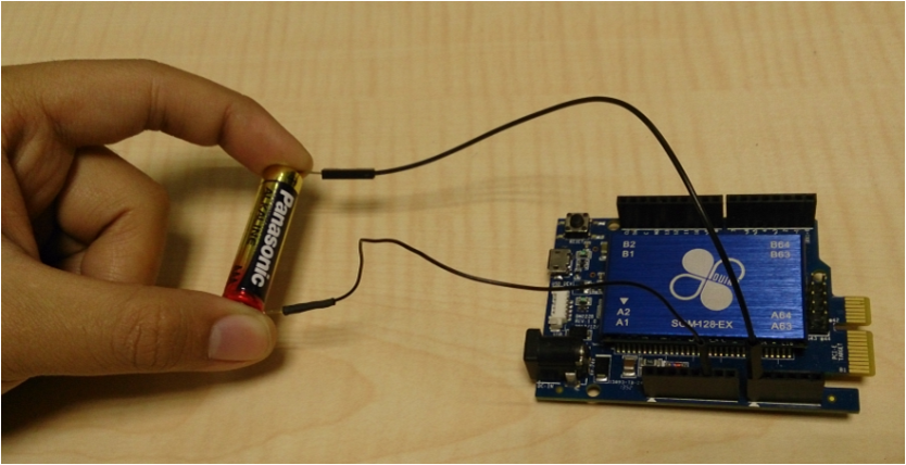
Connection sample
In this sample, we are using an 86Duino Zero to detect a voltage on an AAA battery. Connect the positive of the battery to one of the pins from AD0-AD5 and the negative of the battery to GND. Now you can call analogRead function to read the voltage on the battery.
More information for A/D, Please see this document.
G. I2C connector
86Duino Zero provides a set of I2C, SDA and SCL pins, see setup below:
You can use Wire library in the 86Duino Coding develop environment to control I2C connector. Zero can support I2C standard mode (up to 100Kbps), fast mode ( up to 400Kbps), high-speed mode ( up to 3.3Mbps). Raise resistance on both SCL and SDA pins (see Wiki ) according to I2C specifications. There is a relationship between raising resistance and I2C speed mode. For Zero, at 100Kbps and 400Kpbs speed mode, we suggest adding a 4.7k ohm to raise resistance. At 3.3Mbps speed mode, a 1K ohm resistor should be added.
Connection sample
We can use a RoBoard Module RM-G146 9-axis inertia sensor as an example to show how it can connect to I2C connector on a 86Duino Zero. See RM-G146 pin assignment:
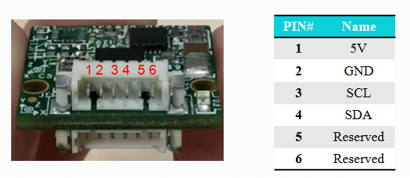
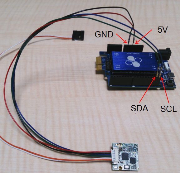
Because the I2C channel in RM-G146 has already raised the resistance, we don’t need to add more resistance. All we need to do is connect the Zero’s 5V output pin to RM-G146’s 5V input. Both GND should be connected. Also, the I2C channel needs to be connected on both sides. Now the Zero and RM-G146 can communicate with each other through I2C.
H. PWM connectors
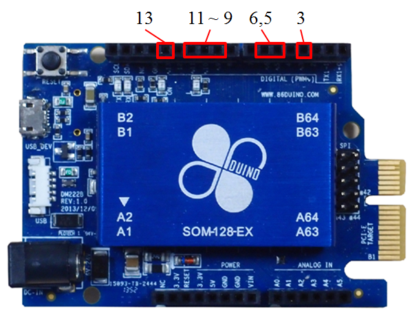
86Duino Zero provides 7 PWM output channels (shared with GPIO pins), and the locations are pins 3, 5, 6, 9, 10, 11, 13.
You can call analogWrite function in the 86Duino Coding development environment to make these Pins send out a PWM signal. PWM channels in the Zero will allow up to 25MHz or 32 bit resolution output signal. But in order to be compatible with the Arduino, the default frequency is 1 KHz and the resolution is 8 bits.
The PMW frequency will be fixed to 1 KHz from the analogWrite function, but you can call analogWriteResolution functions to raise the resolution to 13 bits. If you need to make the PWM send out other frequencies, you can use the TimerOne function to send out a PWM signal with the highest frequency you can send out being 1MHz.
If you need more information regarding PWM, Please see this document.
I. TTL (UART TTL)
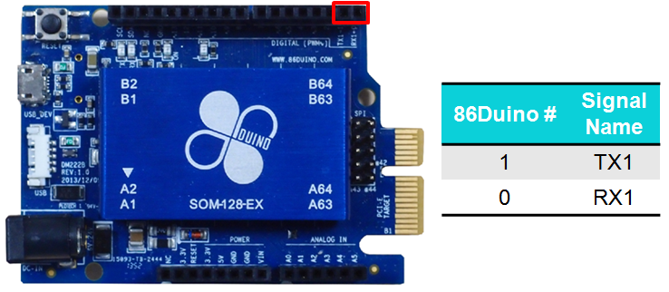
86Duino Zero provides one set of UART TTL, TX1 (1)/RX1(0). The baud rate can reach 6Mbps and you can use Serial1 function to receive or send data. UART TTL connector location is shown below:
Please note, the UART signal has LVTTL and a voltage level (0-3.3V). Please do not connect 12V from RS232 directly as to prevent burning out the pins.
The UART TTL from Zero has full-duplex and half-duplex mode. When it work as half-duplex mode it can connect with half-duplex robot directly unlike Arduinos and Raspberry Pi, which need additional interface circuits to convert full-duplex to half-duplex. UART TTL’s half-duplex can be switched from begin function in the Serial1 function group under 86Duino sketch program.
Connection sample
Will show you how to connect Zero and servos in Dymanixel AX-12+ from Robotis. The following is the AX-12+ and pin assignment:
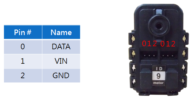
Since the AX-12+ use half-duplex UART TTL to communicate, we will use the Zero’s UART which should be in half-duplex UART as well. In half-duplex mode, UART’s TX pin can be used for receiving and sending serial data. The RX will not be used at all. So we just connect AX-12+’s DATA pin with Zero’s TX1 pin, VIN pin and GND pin with each other. See following picture:
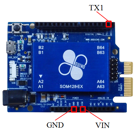
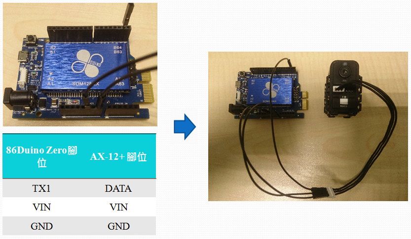
After connecting these wires, use the Serial1 function in 86duino sketch program so the unit can communicate with the AX-12+. Note: Zero and AX-12+ baud rate need to be set up exactly the same in order to communicate. Also, the VIN needs to provide the correct current (7V-10V) to make the servos work for AX-12+ movement.
J. SPI connectors
86Duino Zero provides a set of SPI connectors with location mirroring the Arduino Leonardo. Also, CS connectors have been added for SPI communication.
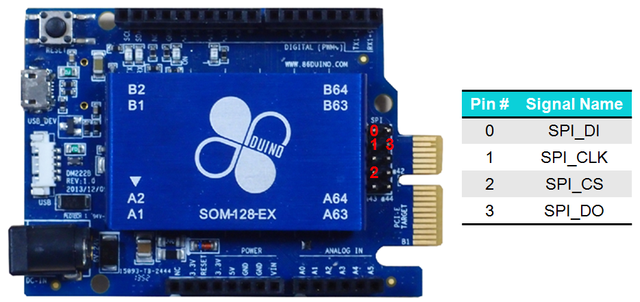
You can use the SPI library in the 86Duino Coding development environment to control SPI connection.
K. LAN Ethernet connectors
86Duino Zero provides a LAN connector on the bottom and supports 10/100Mbps.You can use Ethernet library to receive and send data. The location for the connectors and pin assignment are shown below:
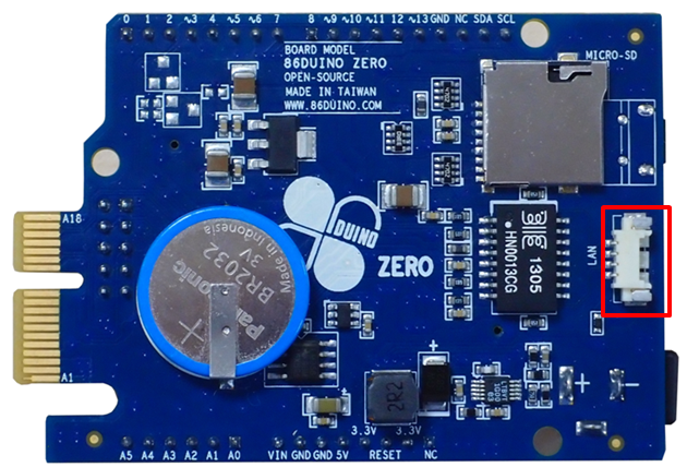
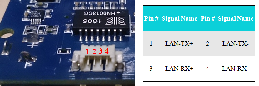
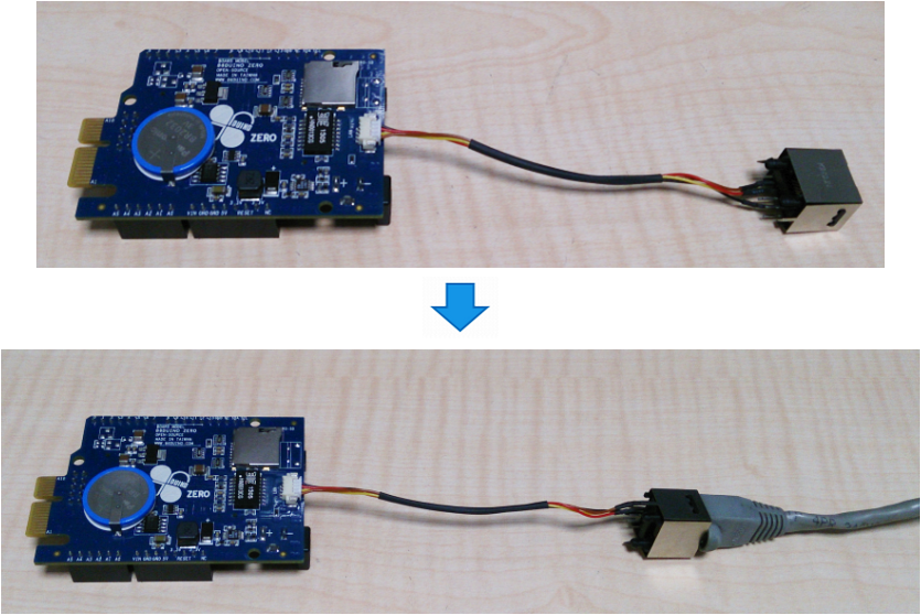
The connector for the LAN is a 4 pin connector with 1.25mm in size. You will need an RJ45 cable (included with the 86Duino Zero Cable Set) to connect the Ethernet. In order to make connecting easier, the designer put the RJ45 base into another location for easy connection and not by the control board itself.
Connection sample
Below is the cable that comes with 86Duino Zero Cable Set and used to connect to a RJ45 connector and Ethernet line.
L. USB 2.0 Port
The 86Duino Zero has one USB 2.0 Host port which can be used to connect a USB device (USB keyboard or mouse). We can use USB Host library in 86Duino Coding development environment to restore USB keyboard and mouse. When you install either Windows or Linux in Zero, the USB port can also be connected to USB Wi-Fi card and USB camera in order to have internet and video function. USB port and pin assignment below:
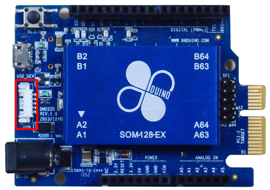
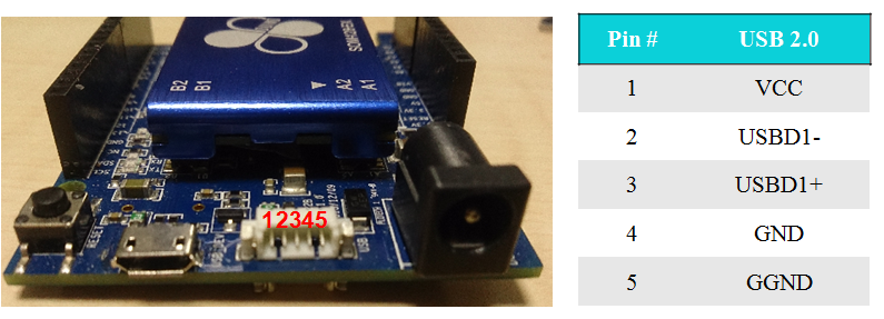
USB connector is a 1.25mm with 5 pins so you will need a USB cable with wiring (86Duino Zero Cable Set will include a USB Type A converting cable) to connect a USB device.
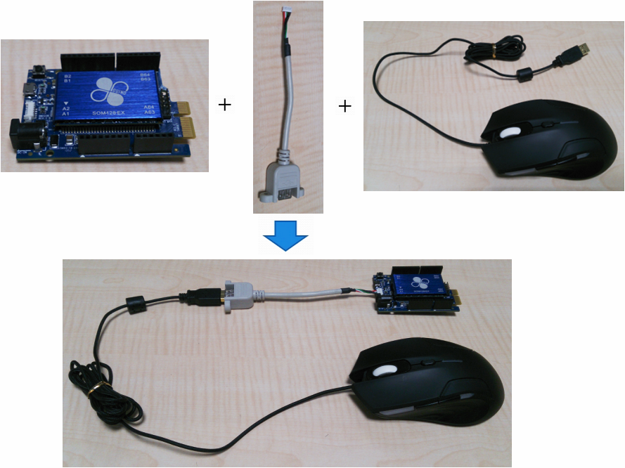
Connection sample
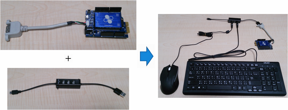
The cable can be seen connected to a USB mouse below:
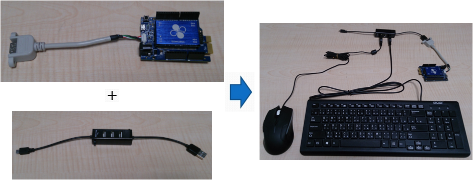
If you need to connect two or more USB devices, a USB Hub can be used. See the following sample to show the USB Hub connect both USB keyboard and mouse:
M. Encoder connector
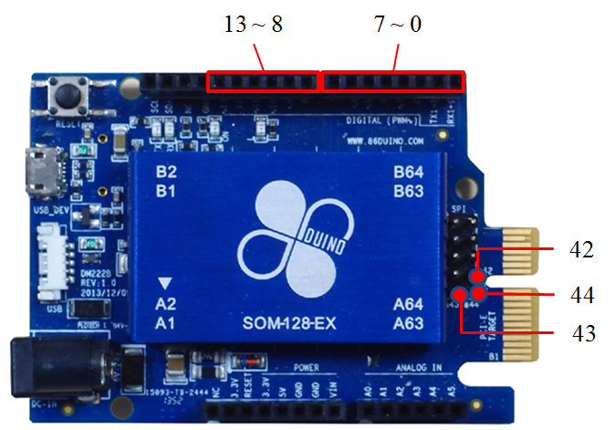
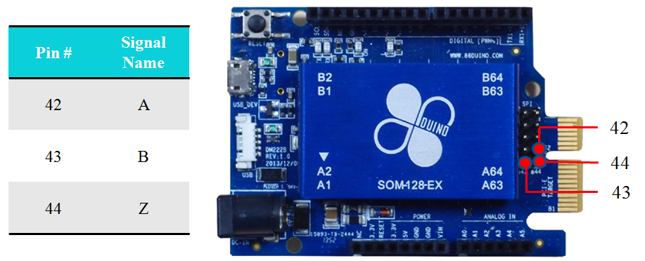
86Duino Zero provides one set of Encoder ports with 3 pins, marked as A, B, and Z:
Encoder ports can be used for reading optical incremental encoders and SSI absolute encoder signals. In 86duino coding development environment, you can use the Encoder library to read the value. The highest input signal frequency is 25MHz for the Encoder port.
Connection sample
We use an AM4096 rotary encoder as a sample to show you how it can connect to 86Duino Zero Encoder port. See the following for AM4096 pin assignment:
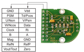
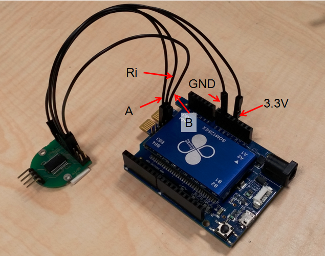
Regarding the output pins, one of them is the output for optical incremental encoder signals in A/B Phase, the symbols for these pins being A, B and Ri. We can connect A, B and Ri from AM4096 connect to 42, 43 and 44 pin on 86Duino Zero and then connect the AM4096 power Vdd to 3.3V. Also, connect the GND from AM4096 to GND on Zero. Now the Zero and AM4096 can communicate with each other by Encoder port, See following:
N. CMOS Battery
Most x86 computer have a CMOS memory to save the BIOS setting and Real Time Clock (RTC) for recording the time and date. The CMOS memory be erased if the power is disconnected. x86 computer motherboards usually include a battery to save the data for the CMOS memory.
86Duino Zero is based on a x86 structure and also includes a CMOS memory and battery.
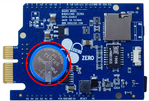
However, the Zero’s CMOS memory only saves the RTC and CMOS band data of EEPROM library, it can’t save the BIOS setting. So even if the battery is not working properly, the Zero still can boot up with BIOS normally, but it may lose the data that was saved in the EEPROM library. Also the Time86 library reads the RTC repeatedly so in order to make sure EEPROM and Time86 are working properly, please do not remove or short the CMOS battery on the board.
O. PCI-E Target connectors
You may notice that the 86Duino Zero board has a connector like PCI-E, see below:
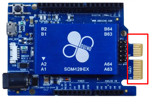
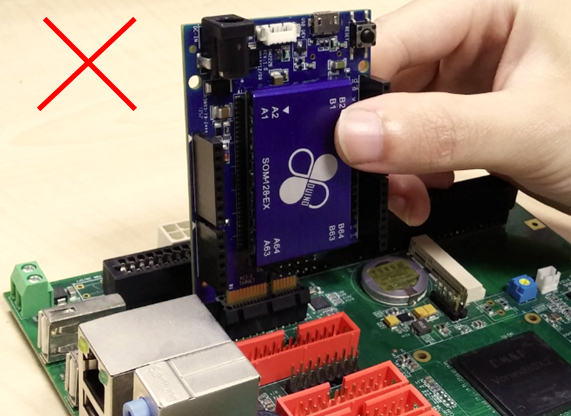
In actuality this connector is for hackers! However, hardware hacking on the Zero is required in order to start its functions. You also need a lot of knowledge on Vortex86E and PCI-E interface. This was made especially for 86Duino enthusiasts since PCI-E golden fingers do nothing unless you know how to start the function. So please do not plug it into a computer motherboard that has a PCI-E slot:
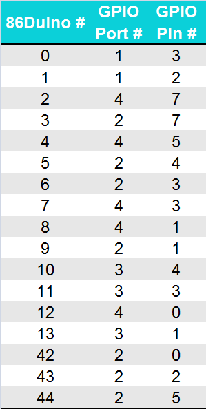
Appendix A: 86duino Zero Pin assignment with Vortex86E GPIO ports
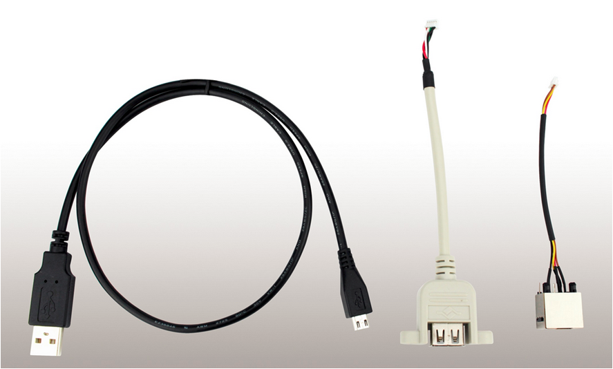
Appendix B: 86Duino Zero Cable Set
86Duino Zero Cable Set includes the following cables, from left to right: micro-USB power cable, USB Host connect cable, RJ45 Ethernet connector.
Appendix C: 86Duino Zero hardware code
The text of the 86Duino reference is licensed under a Creative Commons Attribution-ShareAlike 3.0 License. Code samples in the reference are released into the public domain.