86Duino EduCake Hardware Introduction
Introduction
86Duino EduCake (EduCake) is an open-source microcomputer learning platform built on Vortex86EX, a System-On-Chip (SoC) built with 32-bit x86 processor. The EduCake is designed to be electronically compatible to the Arduino platform. In addition, the EduCake includes Arduino emulation software which enables application codes written for Arduino (sketch) to be compiled and run on the EduCake without modification. In a nutshell, the EduCake is hardware and software compatible to the Arduino platform.
The EduCake is packaged in a compact, yet functional metallic enclosure with an integrated solderless breadboard that exposes I/O pins compatible to the Arduino, designed to help hobbyist and student experiment different electronic circuitries, to learn microcomputer and embedded system, without the need to solder.
In addition to the Arduino compatible I/O pins exposed through the solderless breadboard, the EduCake enclosure provides additional I/O, such as Audio input/output, USB, Ethernet, Serial and SD slot to support SD flash storage card.
Hardware
- CPU: 300 MHz Vortex86EX System-on-Chip with a 32-bit x86 processor (CPU can be overclocked to 500MHz using SysImage)
- RAM: 128 MB industrial-grade DDR3 SDRAM
- Flash: 8 MB internal flash, preloaded with system BIOS and 86Duino firmware
- 10/100 Mbps Ethernet via an RJ-45 connector
- 2 USB host interfaces (Type A USB female connector)
- 1 SD slot
- Integrated Realtek ALC262 HD audio chip with 1 Audio output and 1 microphone input
- 1 RS-232 serial port (DB-9 connector)
- The 5V power input connector is a Type B micro USB female connector, which is also the interface to the development computer to upload application code (sketch) from the 86Duino Coding IDE. And there is a power ON/OFF switch and a power indicator LED.
- 26 digital I/O pins (GPIO)
- 3 TTL UART (Serial interface)
- 2 Encoder interfaces
- 6 A/D input pins
- 9 PWM output pins
- 1 I²C interface
- 5V and 3.3V output pin
- System reset pin
- Dimension: 78.6mm x 78mm x 28.3mm
- Weight: 280g
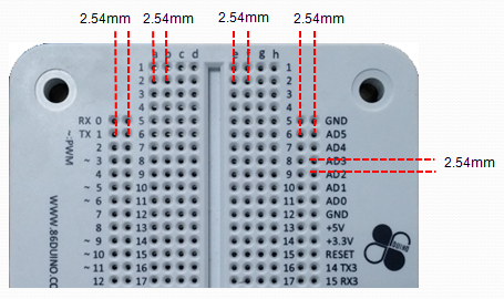
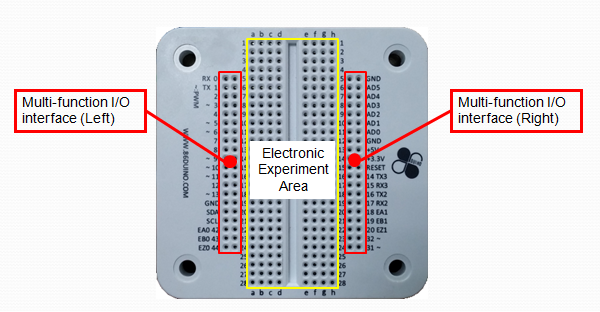
- The EduCake’s Arduino compatible I/O pins are accessible through the integrated solderless breadboard, with 2.54 mm spacing between the pins, as shown in the following figure:
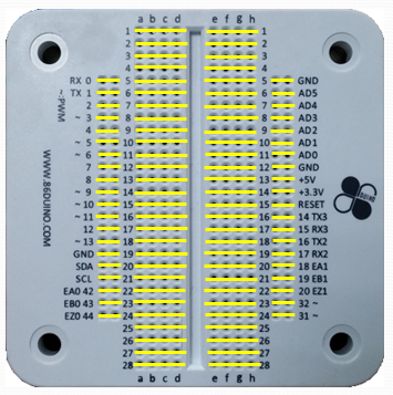
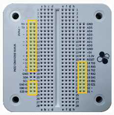
The following figure shows the connectivity for the pins on the solderless breadboard, where each yellow-line marks the pins that are connected (shorted):
I/O Interface Layout
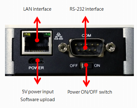
In addition to the Arduino compatible I/O accessible through the solderless breadboard, the EduCake is built with common computer interfaces on the front and back of the unit, as shown below:
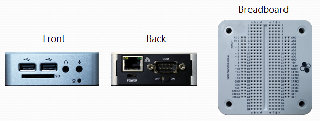
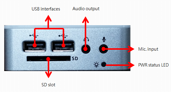
Interface on the front
Interface on the back
Solderless Breadboard
Arduino compatible I/O pins are linked to the 2 left-most and right-most columns on the breadboard, marked in Red as shown below:
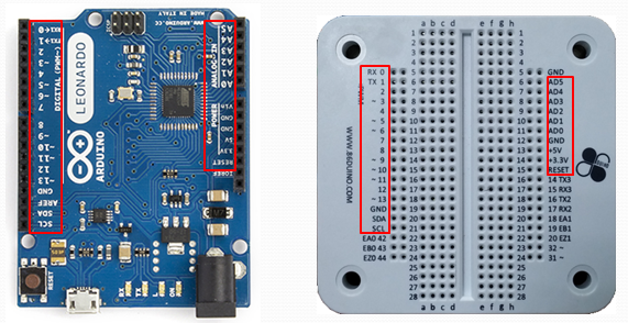
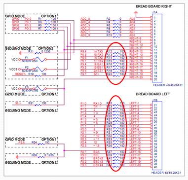
To be compatible and take advantage of the vast technical references and tutorials available for the Arduino platform, the I/O pins on the EduCake are organized in the same sequence as an Arduino Leonardo, as shown in the figure below:
Introduction to EduCake I/O Function and Feature
1. Power System
EduCake is powered by external 5V power source. The integrated power regulator generates the voltages needed by the electronic circuit within the EduCake. An on/off switch is included in the design. Circuitry for the power system and the on/off switch is shown in the following figure:
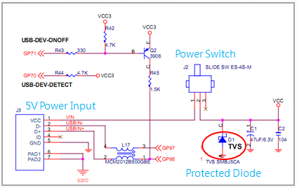
While the EduCake is using a simple power circuitry, from the above schematic, you can see the circuit includes Transient Voltage Suppresser (TVS) diode to protect the internal circuit against power surge during initial power on.
Power Input
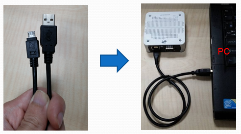
EduCake requires +5V DC power input to function. You can power EduCake using a micro-USB to type A USB cable, from a PC’s USB interface, as shown in the following figures:
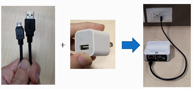
You can also power EduCake using common USB charger for smartphone or portable USB power source as the following figures:
Without any external USB device attached (ex. USB keyboard or USB mouse), EduCake requires at least 400mA to operate. An USB 2.0 interface on the PC can provide up to 500 mA. External USB devices or electronic components on solderless breadboard attached to the EduCake will increases the power needed for EduCake to operate properly. In this case, it is not suitable to power EduCake by using USB 2.0 interface on the PC, consider to power EduCake by an USB 3.0 interface that can provide up to 900 mA on the PC.
Note: USB interface on some of the older PC is designed to provide less than 500 mA of power and may not be sufficient to support EduCake’s power requirement. You may not boot or upload sketch via 86Duino IDE to EduCake by using such USB interface. In this case, recommend to retry on another PC.
Power-on the EduCake
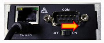
To power on EduCake, connect to the required power source and move the power on/off switch to the “ON” position, as shown below:
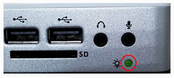
The power indicator LED on the front of the EduCake should turn on to indicate power is flowing through the unit and enables EduCake to function.
Power Output
The EduCake’s integrated breadboard has 5V and 3.3V output that can function as power source for experimental circuit. The 5V output on the breadboard is linked to the 5V power input on the EduCake. The 3.3V output is through an internal regulator and able to supply up to 400mA current.
Note: For example, when 5V 1000mA power source is used to power the EduCake, 400mA is needed for EduCake, the remaining 600mA is available to support the 5V output pin on the breadboard (assuming there isn’t other USB device attached to the EduCake). As for the 3.3V output pin, the output current is limited to 400mA, regardless of the high current source available from the external power supply.
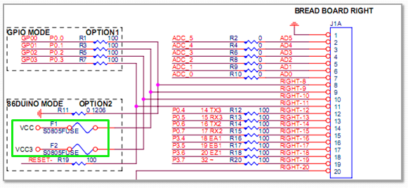
The 5V and 3.3V output pins on the breadboard are shown in the following figure:
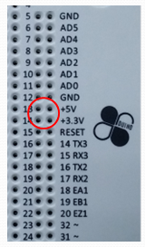
To prevent damage to the EduCake’s internal component caused by over current through the 5V and 3.3V output pins, there is a 1.0A fuse added to each of these 2 pins, as shown in the figure below:
When working on circuitry that expect to draw higher current, such as to drive a servo or motor, it’s best to incorporate external power source, and make sure the external power source is sharing the same ground as the EduCake.
2. SD slot
The SD slot on EduCake support SDHC card, up to 32GB. SDXC is not support.
Note: When installing Windows, Linux or other OS to boot from the SD storage card, the SD storage card’s read/write speed directly impact system performance and boot up time. It’s recommended to use Class 10 SD card.
The SysImage utility is provided to enable you to format and configure SD storage card to boot 86Duino firmware. It has many advantages by booting from SD card on EduCake, see the detail here.
Boot sequence
During power on, the EduCake’s system BIOS search for bootable file partitions from 3 different sources: SD storage card, USB storage and Internal flash storage. Boot sequence: SD storage card is first, then USB storage and finally is internal flash storage.
During power on, when a bootable SD storage card is inserted, the EduCake will boot from the SD storage card. Otherwise, it will search for bootable storage attached to the USB interface. When storage devices are not attached to the SD slot and USB interfaces, EduCake will boot from the internal flash storage.
Note: When non-bootable SD or USB storage is attached to the EduCake, it prevent the EduCake from booting from the internal flash storage, causing the system to hang. Simply fix the non-bootable storage and reset power to boot.
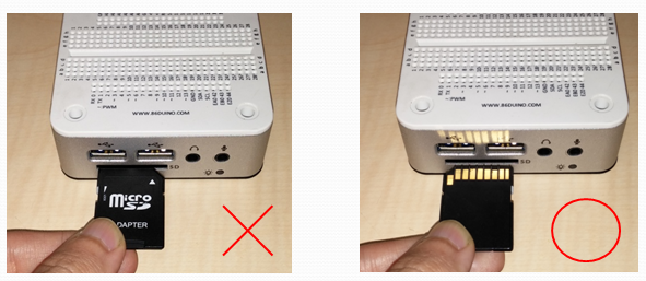
SD Card Insertion Direction
SD card is small. The connector mechanism inside the SD slot is fragile and can damaged when an SD card is forced in the wrong direction. Make sure to insert the SD card in the correct direction, as shown in the figure below:
3. GPIO Pins (Digital Input and Output Pins)
The EduCake’s GPIO pins are positioned on the left-most and right-most column on the breadboard, with marking to identify the pins, 0 ~ 20, 31, 32, 42, 43 and 44, totaling 26 pins, as shown in the figure below, where you can call the digitalWrite() function to set each pin to HIGH or LOW and call the digitalRead() function to read the pin status.
Each of the GPIO pin can be configured to function as input or output, by calling the pinMode() function with proper parameter.
When a GPIO pin is configure to function as output, the PIN will output 3.3V when set to HIGH and 0V when set to LOW. The maximum current each pin is capable to output is 16mA.
When configured as input, each GPIO pin supports 0 ~ 5 voltage range.
Each of the EduCake’s GPIO pins is designed with additional circuit to protect against ESD (Electrostatic discharge) and overvoltage, along with an inline 100 Ohm current limiting resistor to protect against damage to the internal components, as shown in the following figure:
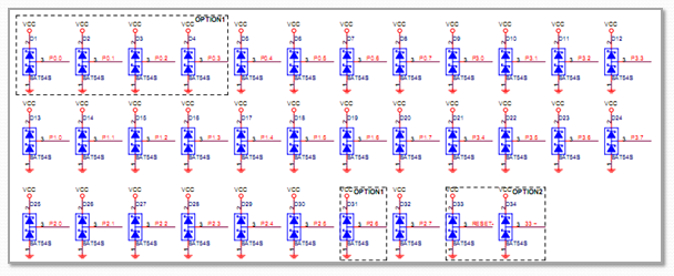
Note: While there are added circuitries to protect these GPIO pins, its ability to protect is limited. High voltage, high current and short will cause permanent damages. It’s good practice to be careful and implement electronic components and power source within the supported range.
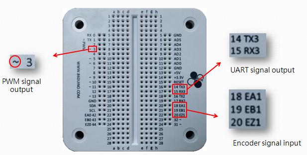
Similar to the Arduino platform, some of the GPIO pins on the EduCake have multiple functions. Pin with the “~” marking indicate it’s capable to output PWM signal. Pins with the “RX” or “TX” marking indicate these are UART interface. Pins with “EA”, “EB” or “EZ” marking indicate it’s capable to handle Encoder input signal, as shown in the following figure:
For more information about GPIO, refer to Fundamental Hardware Concepts.
4. RESET Pin
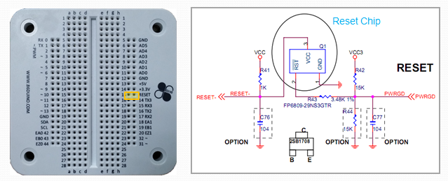
The reset pin, when set to LOW, triggers the EduCake to restart (reboot). The Reset pin for the EduCake is accessible on the solderless breadboard, which is linked to the processor module’s reset chip, as shown in the following figure:
Sample Reset Circuitry
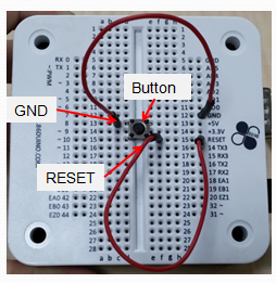
One of the simplest circuit to use the RESET pin is to use a push button, connecting one side to the RESET pin and the other side to ground. When the button is pressed, the RESET pin is connected to ground, bringing the RESET pin’s voltage level to LOW and trigger system reset, as shown in the following figure:
5. A/D Pin (Analog Input Pin)
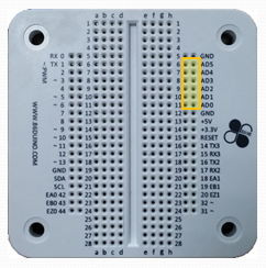
The EduCake exposes 6 A/D input pins on the breadboard, AD0 ~ AD5, as shown in the following figure:
Each of the 6 A/D input is capable to handle 11-bit resolution analog input. You can call the analogRead() function to read each of these A/D input. To maintain Arduino platform compatibility, the analogRead() function reads 10-bit resolution data from the A/D pins. You can use the analogReadResolution() function to increase the resolution up to 11-bit.
Note: The input voltage range for these A/D input is 0V ~ 3.3V. It’s important to keep input voltage to each of these A/D pins within 3.3V. When the input voltage for anyone of these A/D exceed 3.3V, it will create unpredictable result on all A/D pins. In the worst case scenario, it can permanently damage these A/D input.
Sample A/D Input Circuitry
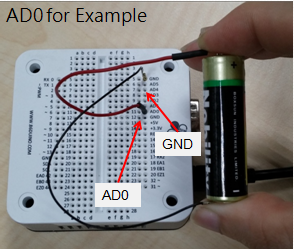
The sample circuit is designed to detect voltage level for an AA battery. Connect the battery’s positive end to one of the A/D pin, AD0 ~ AD5. Connect the battery’s negative end to the GND signal on the EduCake. Then, you can use the analogRead() function to read the AA battery’s voltage level, as shown in the following figure:
For more information about A/D input, refer to Fundamental Hardware Concepts.
6. I2C Interface
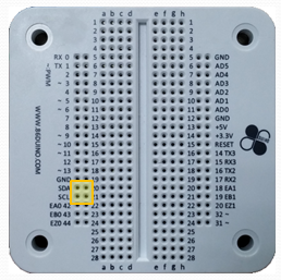
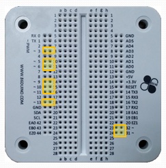
The EduCake exposes an I2C interface through the solderless breadboard. From the 86Duino Coding IDE, you can use call function within the Wire library to access the I2C interface. The two pins with “SDA” and “SCL” marking on the breadboard are I2C interface, as shown in the following figure:
EduCake’s I2C interface support standard mode (up to 100Kbps), fast mode (up to 400Kbps) and high-speed mode (upto 3.3Mbps), 3 different modes to communicate with external devices. According the I2C specification, when connect to external device, both SCL and SDA pins should be connected a pull-up resistor (refer to I2C Wiki for more details). Value for the pull-up resistor vary depending on the I2C transmission speed. To support 100Kbps and 400Kbps modes, we recommend that you add a 4.7K Ohm pull-up resistor. To support 3.3Mbps mode, we recommend that you add a 1K Ohm pull-up resistor.
Sample I2C Circuitry
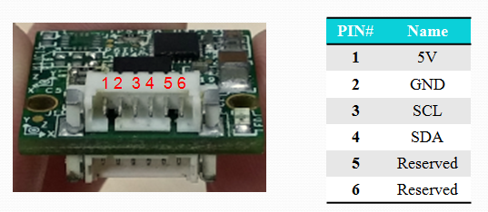
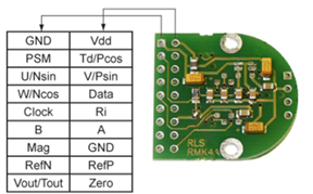
For this sample circuit, we will use the RoBoard RM-G146 9-Axis motion sensor module, connecting this module to the EduCake via the I2C interface. The following figure shows the module’s pin out:
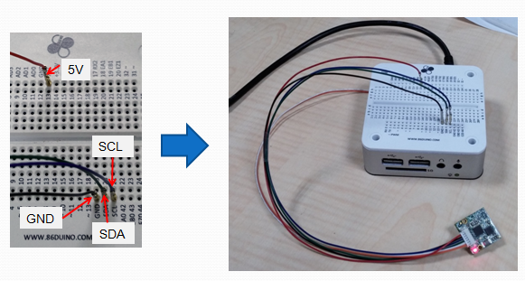
Since the RM-G146 module is built with integrated pull-up resistor, we can connect the module directly to the I2C interface on the EduCake, as follow:
- 5V output from the EduCake connect to 5V input on RM-G146
- Connect EduCake GND to RM-G146 GND
- Connect EduCake I2C to RM-G146 I2C
7. PWM Output
There are 9 GPIOs on the EduCake capable to output PWM signals, pin 3, 5, 6, 9, 10, 11, 13, 31 and 32. From the 86Duino Coding IDE, you can call analogWrite() function with proper parameter to control each of these Pins to output PWM signal. EduCake is able to output PWM signal up to 25Mhz or 32-bit resolution. To maintain compatibility to the Arduino platform, EduCake is configured to output 1KHz 8-bit resolution PWM signal.
The following figure mark the pins capable to output PWM signal on the EduCake:
The analogWrite() function is designed to output PWM signal at 1 KHz fixed and cannot be changed. To output PWM signal at resolution, up to 13-bit, you can use the analogWriteResolution() function.
To output PWM signal at different frequency, you can use TimerOne library to output PWM signal, up to 1 MHz.
For more information about PWM, refer to Fundamental Hardware Concepts.
8. TTL Serial Interfaces (UART)
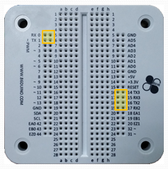
The EduCake has serial interfaces available, TX1(1)/RX1(0), TX2(16)/RX2(17) and TX3(14)/RX3(15), each can support baudrate up to 6Mbps. To communicate with external device via these serial interfaces, you can use the Serial library to transmit and receive data.
The three TTL UART interfaces are accessible from the breadboard, as shown in the following figure:
Note: The 3 TTL UART interfaces on the EduCake is at LVTTL voltage level (0 ~ 3.3V). Do not connect one of these interfaces to an RS-232 port, which is at 12V and will damage the TTL UART interfaces.
9. RS-232 Serial Interface
There is one RS-232 interface on the EduCake, through a DB-9 connector on the back of the unit, which can support data transfer rate up to 1.5Mbps. You can use the Serial232 library to transmit and receive data through the RS-232 serial port.
The following figure shows the connector pin-out and pin description for EduCake’s RS-232 serial interface:
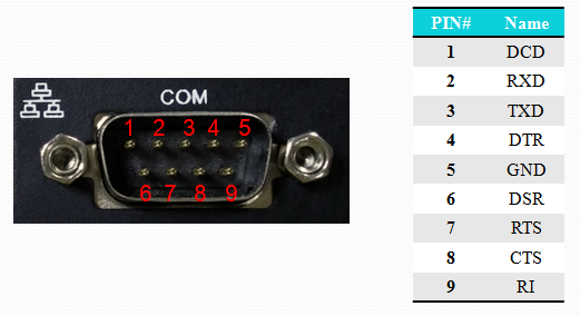
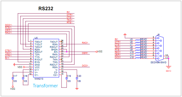
Note: Voltage level for the TTL UART interface is between 0 ~ VCC (0 ~ 3.3V or 0 ~ 5V). Whereas, voltage on the RS-232 interface range from -12V to +12V via a voltage transformer like following figure. Connecting a TTL UART interface to RS-232 will cause permanent damage.
10. LAN Interface (Ethernet)
There is one 10/100 Mbps LAN interface on the EduCake. You can use the Ethernet library to transmit and receive data through the LAN interface.
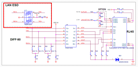
The LAN interface on the EduCake is built with additional chip and transformer circuitry to protect internal components against ESD (electrostatic discharge) and transient voltage, as shown in the following schematic:
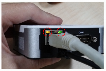
LAN Connection
After power on, connect EduCake to a Local Area Network using an RJ-45 networking cable. If the attached network is working properly, the LAN connector’s LEDs should turn on and start to blink, as shown in the following figure:
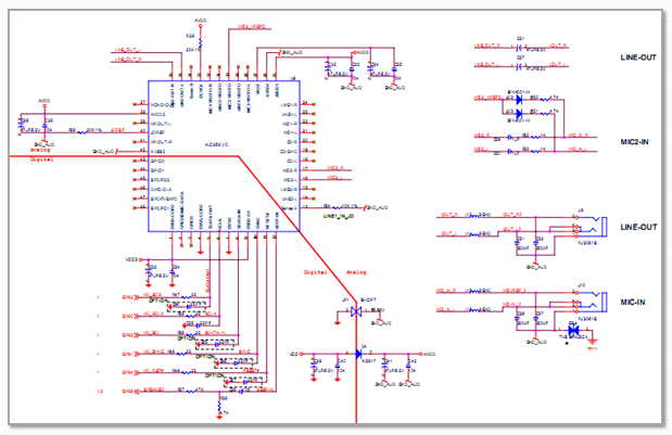
11. Audio Interface
EduCake has integrated audio function using Realtek ALC262 HD audio Codec chip and provides stereo audio output and microphone input interfaces through two 3.5 mm jacks on the front of the unit. You can use function within the Audio library to access the audio function.
Audio function circuitry for the EduCake is shown in the following figure:
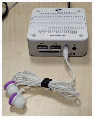
Audio Device Connection
As shown in the following figure, you can attach an earphone to the 3.5 mm audio output jack on the front of the unit:
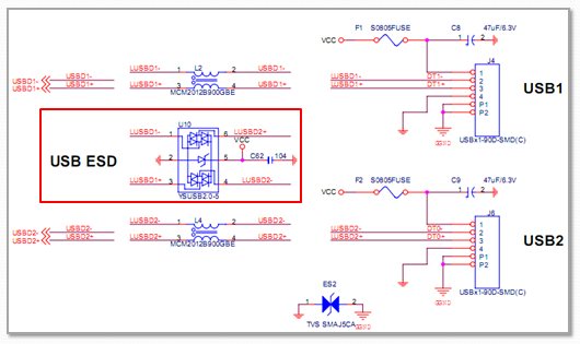
12. USB 2.0 Interface
EduCake is built with two USB 2.0 interfaces on the front side, which can support USB HID (keyboard or mouse), storage and other devices. Under the 86Duino Coding environment, you can use USB Host library to read data from USB keyboard and mouse.
When EduCake is running Windows or Linux operating system, the USB 2.0 interfaces can support USB-WiFi, USB-Camera and other USB devices.
The USB 2.0 interfaces on the EduCake is built with additional component to protect against ESD, as shown in the following schematic:
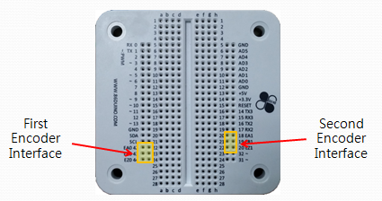
13. Encoder Interface
EduCake is built with encoder interfaces that support incremental and absolute optical encoders. These encoder interfaces can handle up to 25 MHz input frequency. You can use the Encoder library to read data from the attached encoder.
EduCake has two groups of Encoder interfaces accessible on the solderless breadboard, group-1: EA0 (42) / EB0 (43) / EZ0 (44), group-2: EA1 (18) / EB1 (19) / EZ1 (20), as shown in the figure below.
Sample Encoder Wiring
For this example, we use an encoder built with the AM4096 rotary encoder chip. The pin-out for the encoder is shown in the following figure:
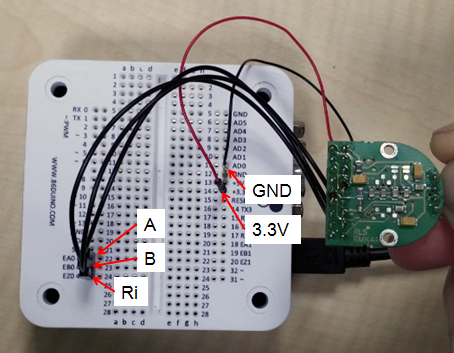
We can connect the incremental encoder signals (A/B phase) from the AM4096 encoder to the EduCake’s encoder inputs. We can connect pins A, B & Ri from the encoder to EA0, EB0 and EZ0 on EduCake’s breadboard. Then, connect the 3.3V output and GND from EduCake to the encoder’s Vdd and GND, as shown in the following figure:
Appendix 1: EduCake Tutorials
- Chapter01: Educake Getting Started – Digital I/O
- Chapter02: EduCake Analog I/O Intro
- Chapter03: PWM Tutorial
- Chapter04: EduCake Serial Port Communication
- Chapter05: Interrupt and Event
- Chapter06: I2C Communication
- Chapter07: Robotic Rover
- Chapter08: LED Matrix
- Chapter09: Intro to App Inventor and Application with Bluetooth Connectivity
- Chapter10: Music Player and Mixer
- Chapter11: Control Robotics Arm with EduCake
- Chapter12: Using Matrix Keyboard with EduCake
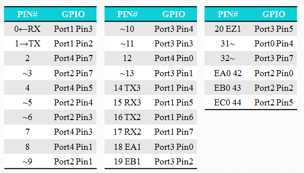
Appendix 2: EduCake GPIO
The following tables provides information showing the mapping between the GPIO pins on the EduCake and the corresponding GPIO port in the Vortex86EX chip.
Appendix 3: 86Duino EduCake Hardware Source code
- Top PCB Schematic
- Bottom PCB Schematic
- Top PCB Gerber Output Files
- Bottom PCB Gerber Output Files
- Bill of Material (BOM) of Top PCB
- Bill of Material (BOM) of Bottom PCB
The text of the 86Duino reference is licensed under a Creative Commons Attribution-ShareAlike 3.0 License. Code samples in the reference are released into the public domain.