Arduino GSM shield 与 86Duino 的连接方式
Arduino GSM Shield 与 86Duino 的连接方式与 Arduino 略有不同,在使用此函式库前,请先参考下面说明将 Arduino GSM Shield 正确连接到 86Duino 上(注意不可将 Arduino GSM Shield 直接堆叠到 86Duino 上)。
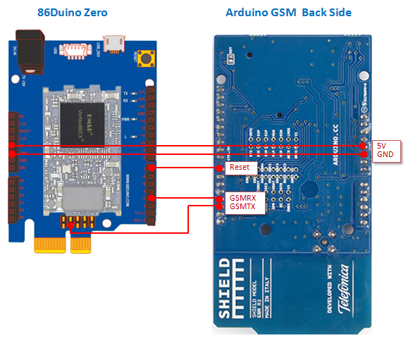
Arduino GSM Shield 主要是以 UART 通讯介面与控制板沟通。它有通讯和控制两种不同功能的脚位,其中,通讯脚位为 GSMTX、GSMRX,请将这两只脚位依序连接到 86Duino 的 digital pin 42、3;控制脚位为 Reset,请将它连接到 86Duino 的 digital pin 7。同时因为 Arduino GSM Shield 需要供应 5V 电源,因此我们将 86Duino 的 5V 输出与 GND 分别接到 Arduino GSM Shield 的 5V 与 GND 脚位,如此即可用 GSM 函式库控制 GSM 模组。
接下来,请参考下面的连接示意图,将 86Duino 和 Arduino GSM Shield 连接起来(这里以 86Duino Zero 为例):
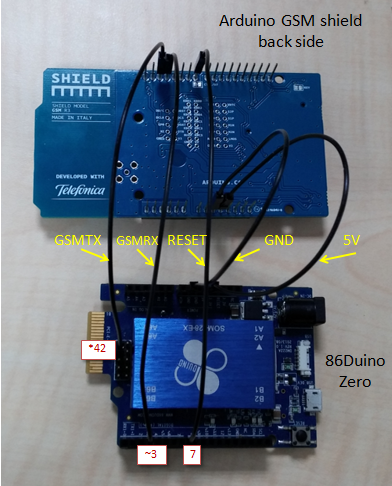
实际连接范例:
另外,在 GSM 函式库有支援另一种传输模式,为 Hardware Serial 模式。在预设情况下,GSM 函式库是工作在 Software Serial 模式下的,启用 Hardware Serial 模式可增加资料在传输过程中的稳定性。以下将介绍如何启用 Hardware Serial 模式,并介绍 Hardware Serial 模式下连接 Arduino GSM shield 的方式。
首先,在 sketch 中,呼叫 useHardwareSerial() 来启用 Hardware Serial 模式(需要在 begin() 之前呼叫),请参考下面范例:
#include <GSM.h>

#define PINNUMBER ""
GSM gsmAccess;
GSMVoiceCall vcs;

void setup() {
    useHardwareSerial(); // 启用 Hardware Serial 模式
    boolean notConnected = true;
    while(notConnected)
    {
      if(gsmAccess.begin(PINNUMBER)==GSM_READY)
        notConnected = false;
      else
      {
        Serial.println("Not connected");
        delay(1000);
      }
    }
    // ....
}

void loop() {
    // ....
}
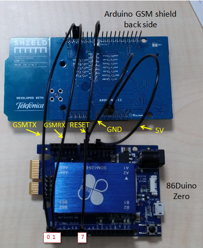
将 sketch 编译并上传至 86Duino 后,请参考下面的连接示意图,将 86Duino 和 Arduino GSM shield 连接起来:

实际连接范例:
The text of the 86Duino reference is licensed under a Creative Commons Attribution-ShareAlike 3.0 License. Code samples in the reference are released into the public domain.