86Hexapod
Project origin
This project originated from the Robot-Skarner project. "It seems that a six-legged robot is easier to make!" The boss was thinking. "Dr. Enzhuo, let's bribe U-Da! Ask him to make a small hexapod robot using 3D printing!" Then Dr. Enzhuo went to U-Da with a dozen Taiwan beers and barbecue skewers. The next day, the world's first 86 small hexapod was born.
Functional Description
This project is implemented using 86Duino Enjoy and 86Duino Zero or 86Duino One. Since sharp tools will be used, children need to be accompanied by their parents during production. The action editor uses 86ME. You don't need to write any program to make the 86 little six-legged animal move!
Prepare materials
- One 86Duino One or 86Duino Zero
- 12 Tower Pro SG90 servos (you can prepare more as spares)
- 3D printer (this project uses ENJOY)
- 2mm x 4mm screws
- 2mm x 8mm screws
- 2mm x 15mm screws
- Dupont wire
- Electronic expansion board (only required when using 86DuinoZero)
- Dupont pins
The circuit of the electronic expansion board is quite simple. You can make one yourself. When using a soldering iron, children must be accompanied by their parents. 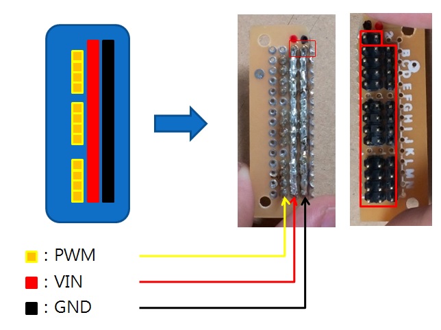
Printing mechanism
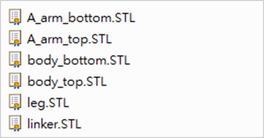
First, download and install 86DuinoRepetier-Host, and refer to Printer ENJOY Quick Start Manual. After the installation is complete, you can download the 86 Hexapod STL File from the Thingiverse website. After decompression, there are six files, as shown below:
Part names and actual corresponding pictures: 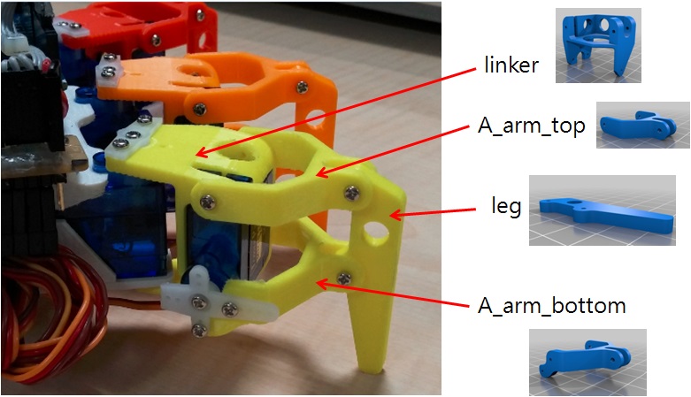
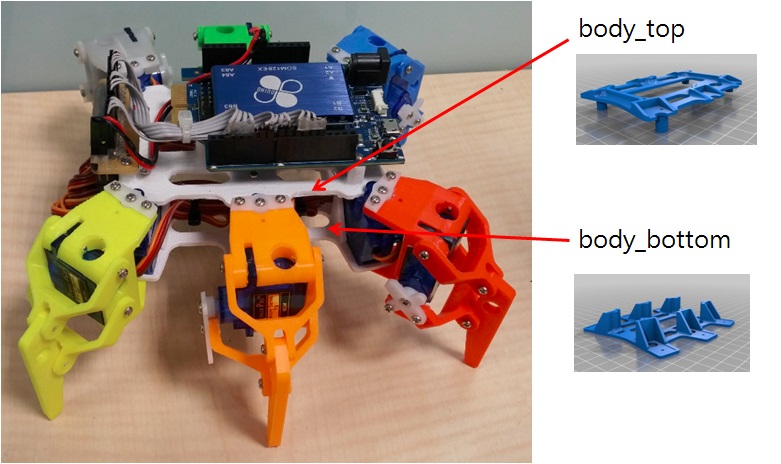 A_arm_bottom, A_arm_top, leg, linker are the combined parts of the hexapod foot. These 4 parts can be combined into a foot. body_top is the upper part of the hexapod body, body_bottom is the lower part of the hexapod body. Open the 86DuinoRepetier-Host that we have installed, and click the Load button to load the 86 small six-foot foot files: A_arm_bottom, A_arm_top, leg, linker
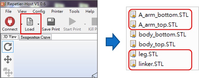
The loaded image is as follows: 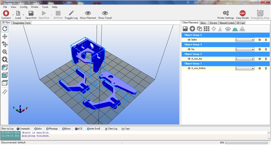 Click Linker and flip the part 90 degrees along the Y axis, as shown below:
 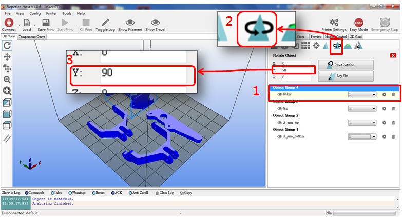 After flipping the linker part, the placement angle should be as shown below:
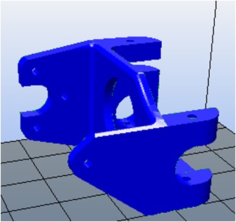
Click A_arm_bottom and flip the part 180 degrees along the Y axis, as shown below: 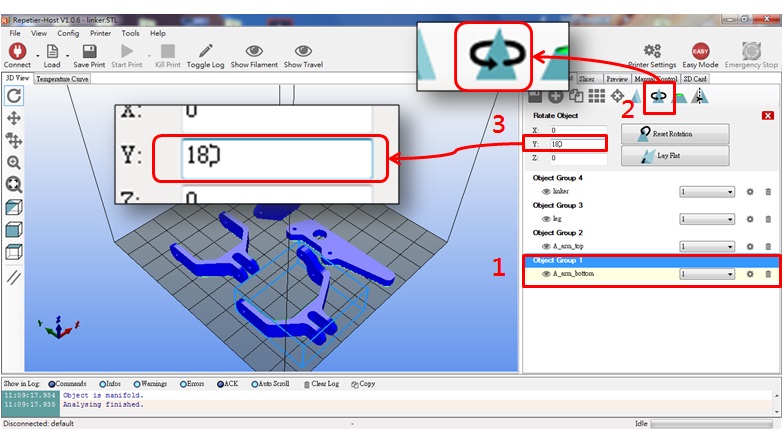 After flipping, the A_arm_bottom part should be placed at the angle shown in the following figure:
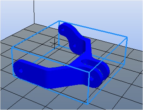
After flipping, the foot part is as follows: 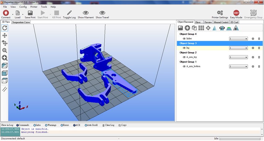 Open the support option and set Support Type to Everywhere:
 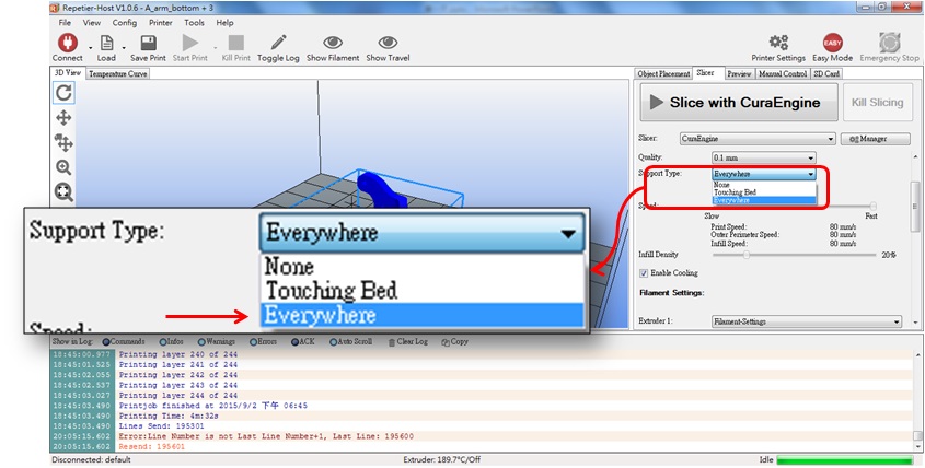 Press the slice button and the slice will be started immediately.
 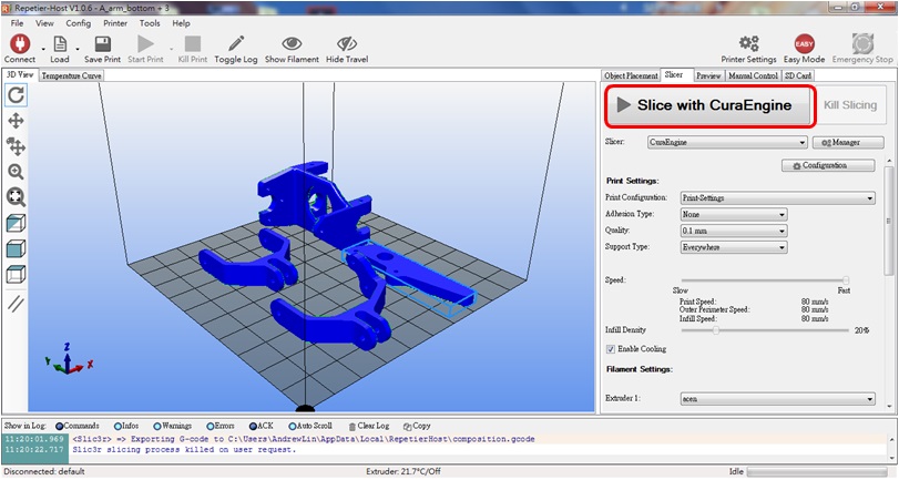 After the slice is completed, a screen similar to the following will appear:
/2018/08/hexapod-14.jpg" alt="zero_size" class="aligncenter size-full wp-image-10054" /> There are two ways to transfer files to 86Duino Enjoy:
Method 1: Use USB cable to transfer
After slicing is completed, just press the print button and 86DuinoEnjoy will start printing immediately 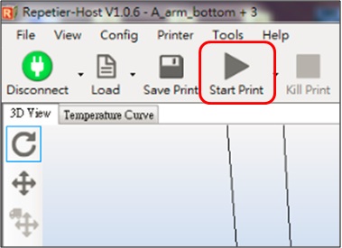
Method 2: Use SD card
Insert the SD card into your computer, After slicing is completed, click the icon below to save the G-code file to SD Card: Select G-Code Editor tab > Press Save button 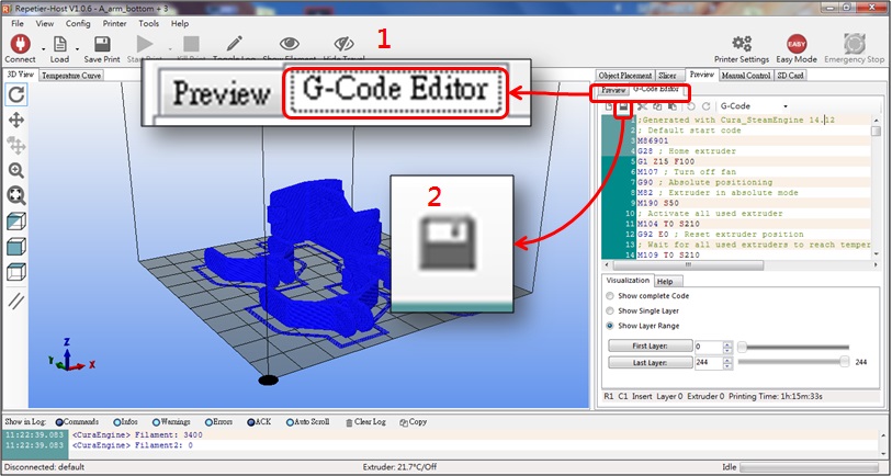 Save the file in the gcode folder in the SD card, change the save file name to auto.gcode, and press Save
 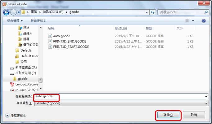 Pull out the SD card from the computer and insert it into the SD card slot on the back of 86Duino Enjoy. Turn on the power of 86Duino Enjoy, and 86Duino Enjoy will automatically read auto.gcode file to start printing! To complete a complete 86 hexapod, you need to print the following: 6 feet 1 upper body 1 lower body
Assembly parts
Before assembling the parts, we must first remove and grind the support materials of the parts: Linker parts, use needle-nosed pliers to remove the following supports: 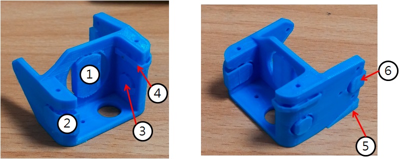 Body_top parts, use needle-nosed pliers to remove the following supports:
 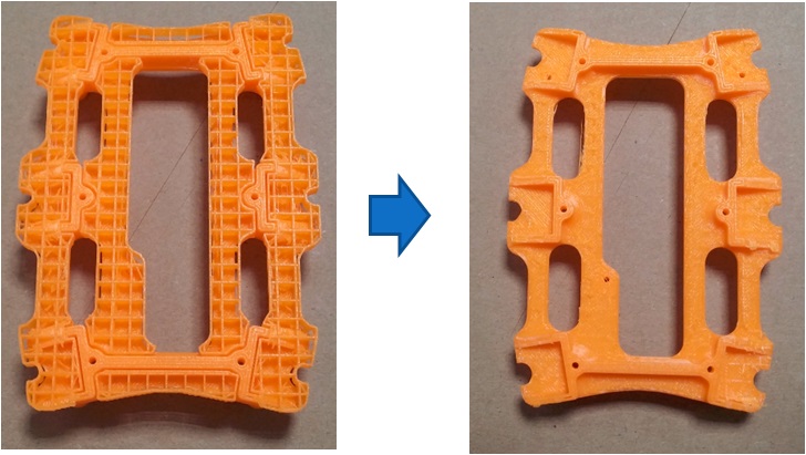 Grind the linker parts and use a file to smooth the uneven surface:
 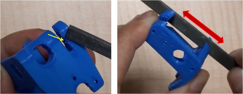 Grind until the servo can be smoothly placed:
 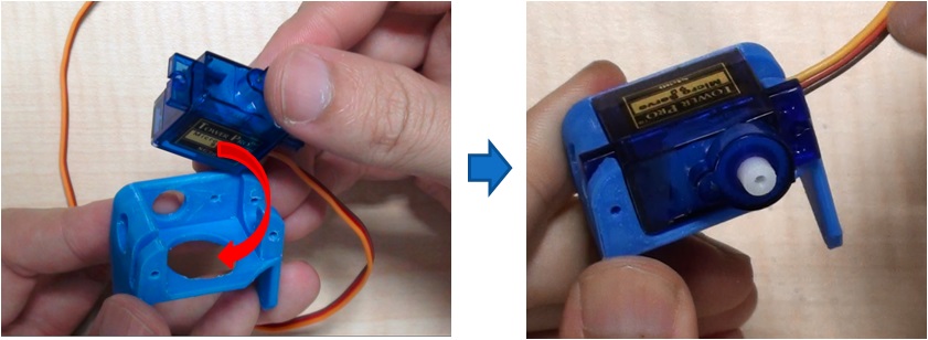 Grind the body_top part, and repeatedly use a flat file to grind the surface after removing the support until the servo can be easily placed:
 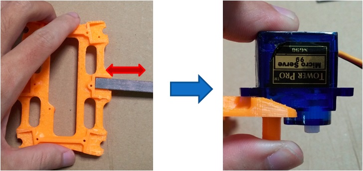 Use a flat file to smooth the contact surface between body_bottom and the servo until the servo can be pressed in smoothly:
 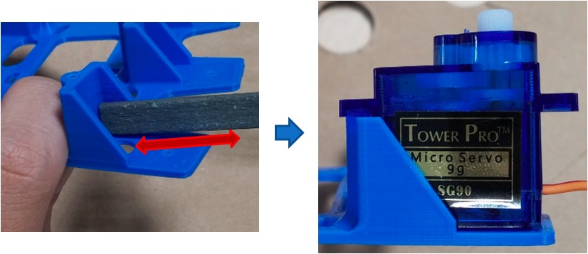 After removing and polishing the parts, we need to drill and tap: The holes that need tapping are shown in the red circle in the figure below: Linker parts:
 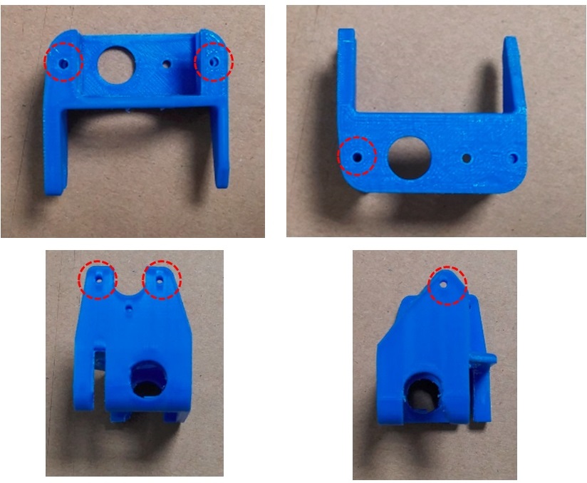 A_arm_bottom, leg parts:
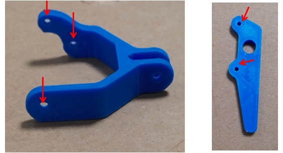
body_top, body_bottom parts:
The holes that need to be drilled are as shown in the red circle in the figure below: Linker, A_arm_bottom, A_arm_top parts: 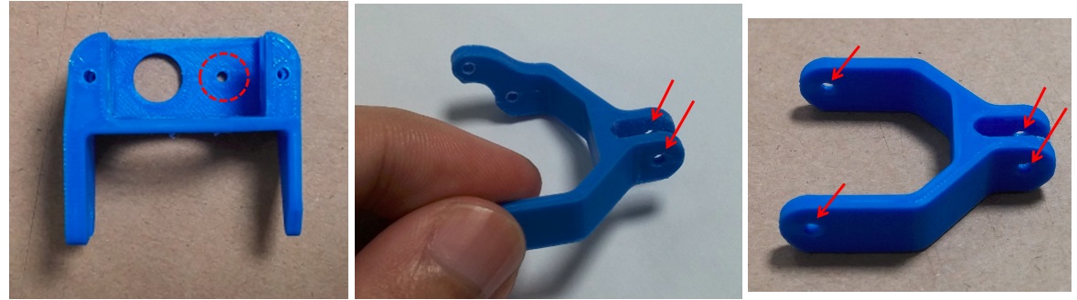 body_top, body_bottom parts:
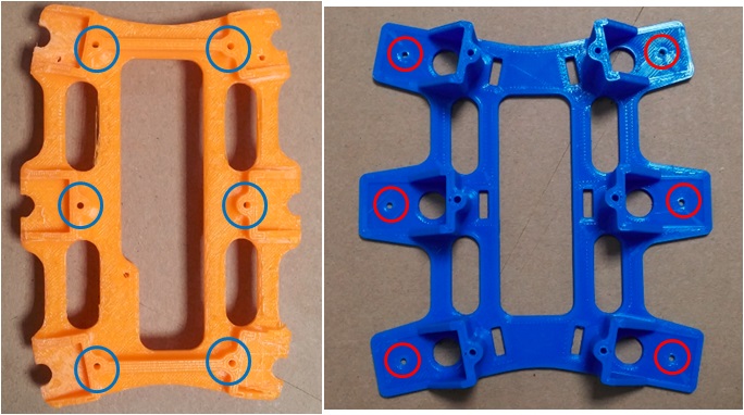
After completion, we can prepare to install the turntable on the servo, but we need to reset the servo first. Zeroing means turning the servo to the center of the movable range. We use the Servo86 library to reset the servo, and use the 86Duino IDE to burn the zeroing program to the 86Duino development board. The following is the sample code:
86Duino Zero Zeroing Program
|
1 2 3 4 5 6 7 8 9 10 11 12 13 14 |
|
86Duino One zeroing program
|
1 2 3 4 5 6 7 8 9 10 11 12 13 14 |
|
After the burning is completed, 86Duino will immediately send out PWM with a duty of 1500us from the specified pin. Then we need to connect the servo to 86Duino.
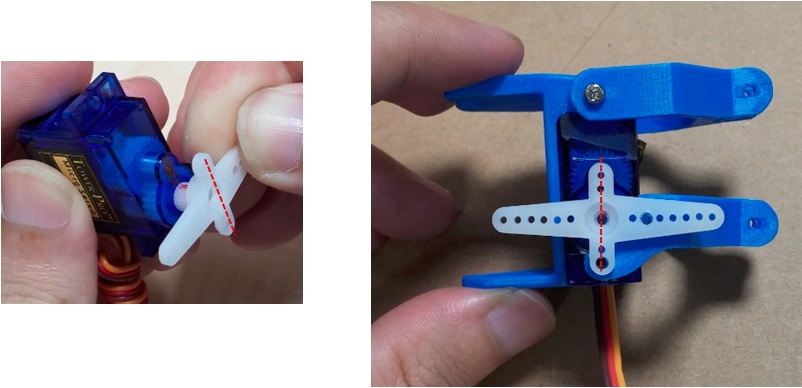
After connecting 86Duino to power/battery, the servo will immediately turn to the midpoint position. At this time, align the short axis of the cross-shaped accessory plate with the midpoint (marked line) and put it on the servo output shaft, as shown in the figure below:
 After completion, you can use screws to lock the parts. The final completed picture is as follows. You can also use diagonal pliers to modify the accessory plate and cut off the longer edges:
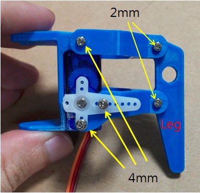
After completing the six legs, you can then assemble the body and place the six servos in the body_bootom, as shown below: 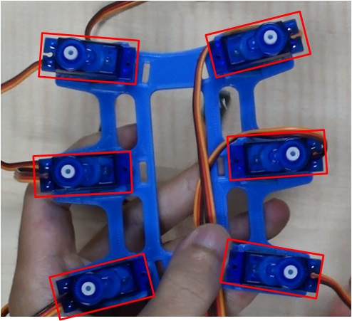
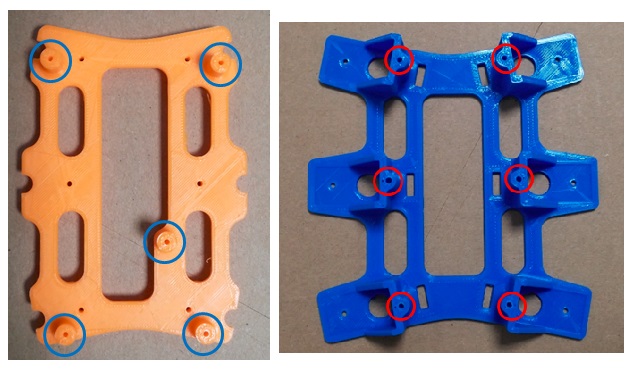
Pull the servo connection lines that fall on the outside to the center of the body and extend them from one end (this is done to facilitate subsequent wiring): 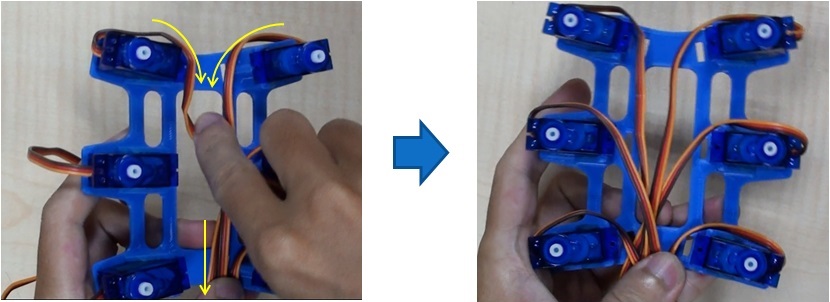 Cover the body_top part and tighten the body_top with 6 15mm screws, as shown in the red circle in the figure below:
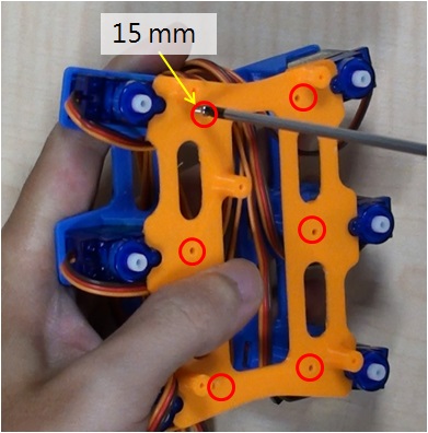
Use a drill to drill holes in the slotted accessory tray (the second hole from the center, as shown in the figure below). A total of 6 slotted accessory trays need to be drilled: 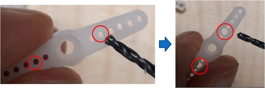 Use the zeroing program provided just now to zero the six servos to the midpoint, and put the straight-shaped accessory plate onto the servo output shaft as shown below:
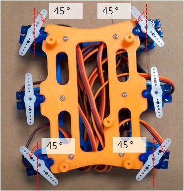
Use 3 2mm x 4mm screws to connect the foot (2 to fix the accessory plate, and the other to fix the linker and body_bottom), and use self-tapping screws to lock the servo straight-shaped accessory plate. You can use diagonal pliers to cut off the protruding part of the straight-shaped accessory plate to increase the appearance: 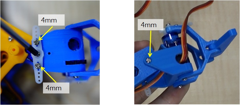 After all 6 feet are locked, it will look like the following picture:
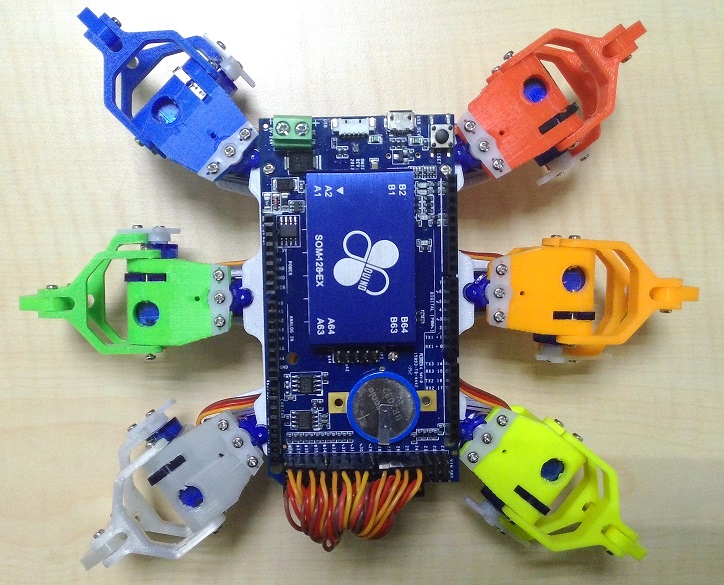
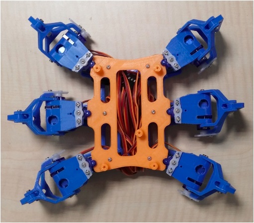
Install the 86Duino Zero development board
Corresponding to the red circle in the figure below, use 3 2mm x 4mm screws to fix the 86DuinoZero on the body_top: 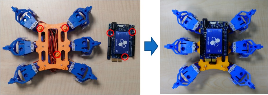 Use 2 2mm x 4mm screws to fix the expansion board:
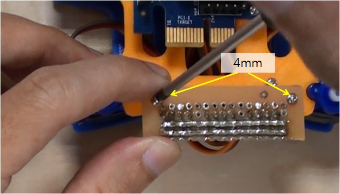
The 86 small six-foot servo number corresponds to the pin on the expansion board as follows: 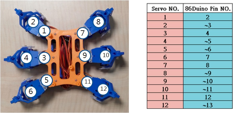 Use 12 yellow (PWM), 1 red (VIN), and 1 black (GND) Dupont wires to connect 86DuinoZero and the adapter board:
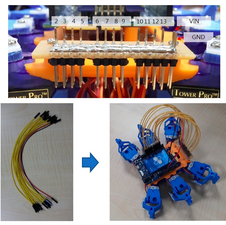
Install the 86Duino One development board
Corresponding to the red circle in the figure below, use 3 2mm x 4mm screws to fix the 86DuinoOne on the body_top part: 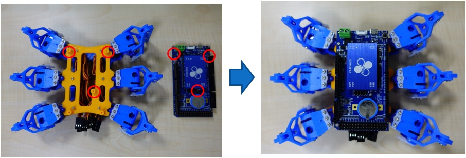 The 86 small hexapod servo number corresponds to the pin position on the 86DuinoOne as follows:
 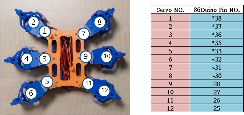 Connect all servo cables to 86DuinoOne:
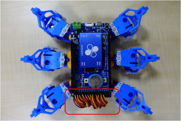
Finally, we will tidy up the exposed cables to make the 86 hexapod look more beautiful. First, pull the exposed servo cables into the body of the 86 hexapod, fold the servo cables back and forth, and fix them to the brackets on both sides with cable ties: 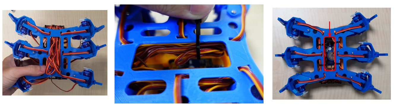 After fixing with cable ties, try to avoid servo cables passing through the red frame in the right picture, because this is the space for placing lithium batteries in the future.
Motion Control
Since 86ME Mk-II has set the 86 Hexapod application project as an example project, you can find the walking action of 86Hexapod.rbm in C:\ProgramData\86ME\examples. After opening the project, remember to fine-tune the offset value of each 86 Hexapod to correct some small errors on the servo.
Results Display
— DEMO Video —
Related Materials
[2] STL structure file download
[3] 86 small six-legged robot DIY course materials:
Self-made Amusement Park Home Page
The text of the 86Duino reference is licensed under a Creative Commons Attribution-ShareAlike 3.0 License. Code samples in the reference are released into the public domain.