AC Phase Control
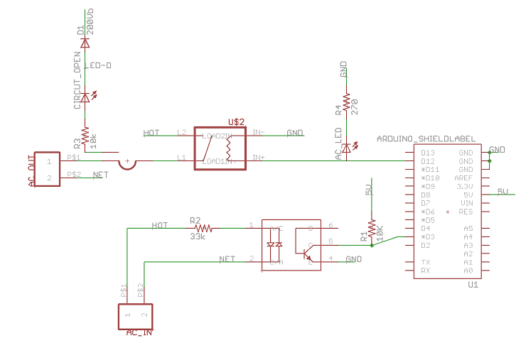
This sketch uses a ‘Random Phase’ or ‘Non Zero Crossing’ SSR (Im using the Omron G3MC-202PL DC5) to act as an A/C switch and an opto-isolataed AC zero crossing dectector (the H11AA1) to give us a zero-crossing reference. This allows the arduino to dim lights, change the temp of heaters & speed control AC motors.
The software uses dual interrupts (both triggered by Timer1) to control how much of the AC wave the load receives. The first interrupt, zero_cross_detect(), is triggered by the Zero Cross detector on pin 3 (aka IRQ1). It resets Timer1’s counter and attaches nowIsTheTime to a new interrupt to be fired midway though the AC cycle. Control flows back to the loop until we have waited the specified time. Then nowIsTheTime pulses the AC_PIN high long enough for the SSR to open, and returns control to the loop.
ACPhaseControl.pde
/* Copyright 2011 Lex Talionis

This sketch uses a 'Random Phase' or 'Non Zero Crossing' SSR (Im using
the Omron G3MC-202PL DC5) to act as an A/C switch and an opto-isolataed
AC zero crossing dectector (the H11AA1) to give us a zero-crossing
reference. This allows the arduino to dim lights, change the temp of
heaters & speed control AC motors.

The software uses dual interrupts (both triggered by Timer1) to control
how much of the AC wave the load receives. The first interrupt,
zero_cross_detect(), is triggered by the Zero Cross detector on pin 3
(aka IRQ1). It resets Timer1's counter and attaches nowIsTheTime to a
new interrupt to be fired midway though the AC cycle. Control flows back
to the loop until we have waited the specified time. Then nowIsTheTime
pulses the AC_PIN high long enough for the SSR to open, and returns
control to the loop.


This program is free software: you can redistribute it and/or modify
it under the terms of the GNU General Public License as published by
the Free Software Foundation, either version 3 of the License, or
(at your option) any later version.

This program is distributed in the hope that it will be useful,
but WITHOUT ANY WARRANTY; without even the implied warranty of
MERCHANTABILITY or FITNESS FOR A PARTICULAR PURPOSE.  See the
GNU General Public License for more details.

You should have received a copy of the GNU General Public License
along with this program.  If not, see <http://www.gnu.org/licenses/>.


Based on:
AC Light Control by Ryan McLaughlin <ryanjmclaughlin@gmail.com>
http://www.arduino.cc/cgi-bin/yabb2/YaBB.pl?num=1230333861

Thanks to http://www.andrewkilpatrick.org/blog/?page_id=445
and http://www.hoelscher-hi.de/hendrik/english/dimmer.htm

Circut Diagram and more information available at:
http://playground.arduino.cc/Code/ACPhaseControl

*/

#include <TimerOne.h>	// Avaiable from http://playground.arduino.cc/Code/Timer1
#define FREQ 60 	// 60Hz power in these parts
#define AC_PIN 9	// Output to Opto Triac
#define LED 13		// builtin LED for testing
#define VERBOSE 1	// can has talk back?

#define DEBUG_PIN 5	//scope this pin to measure the total time for the intrupt to run
int inc=1;

volatile byte state = 255;	// controls what interrupt should be
                            //attached or detached while in the main loop
double wait = 3276700000;	//find the squareroot of this in your spare time please


char cmd = 0;			//Buffer for serial port commands
unsigned long int period = 1000000 / (2 * FREQ);//The Timerone PWM period in uS, 60Hz = 8333 uS
int hexValue = 0;		// the value from serial a serial port(0-0xFFF)
unsigned int onTime = 0;	// the calculated time the triac is conducting
unsigned int offTime = period-onTime;	//the time to idle low on the AC_PIN
int hexInput(int len);		//interprets a hex packet ":XXX" - len hex digits

void setup()
{
    Serial.begin(115200);	//start the serial port at 115200 baud we want
    Serial.println("AC Motor Control v1");	//the max speed here so any
    #ifdef VERBOSE		//debugging output wont slow down our time sensitive interrupt
    pinMode(DEBUG_PIN, OUTPUT);
    digitalWrite(DEBUG_PIN, LOW);
    Serial.println("----- VERBOSE -----");	// feeling talkative?
    #endif
    pinMode(AC_PIN, OUTPUT);		// Set the Triac pin as output
    pinMode(LED, OUTPUT);
    attachInterrupt(1, zero_cross_detect, RISING); 	// Attach an Interupt to Pin 3 (interupt 1) for Zero Cross Detection
    Timer1.initialize(period);
    //	Timer1.disablePwm(9);
    Timer1.disablePwm(10);
}

void zero_cross_detect()	// function to be fired at the zero crossing.  This function
{				// keeps the AC_PIN full on or full off if we are at max or min
    Timer1.restart();	// or attaches nowIsTheTime to fire at the right time.
    state=B00000011;
    #ifdef VERBOSE
    digitalWrite(DEBUG_PIN, HIGH);
    #endif
    if (offTime<=100)			//if off time is very small
    {
        digitalWrite(AC_PIN, HIGH);	//stay on all the time
        state=0;			// no update this period
        #ifdef VERBOSE
        //Serial.print("Full on\t");
        #endif
    }
    else if (offTime>=8000) {		//if offTime is large
        digitalWrite(AC_PIN, LOW);	//just stay off all the time
        state=0;			//no update this period
        #ifdef VERBOSE
        //Serial.print("Full off\t");
        #endif
    }
    else	//otherwise we want the motor at some middle setting
    {
        Timer1.attachInterrupt(nowIsTheTime,offTime);
    }
    #ifdef VERBOSE
    digitalWrite(DEBUG_PIN, LOW);
    #endif
}		// End zero_cross_detect

void nowIsTheTime ()
{
    #ifdef VERBOSE
    digitalWrite(DEBUG_PIN, LOW);
    #endif
    if (state==1)		//the interrupt has been engaged and we are in the dwell time....
    {
        digitalWrite(AC_PIN,HIGH);
        wait = sqrt(wait);		//delay wont work in an interrupt.
        if (!wait)                      // this takes 80uS or so on a 16Mhz proc
        {
            wait = 3276700000;
        }
        digitalWrite(AC_PIN,LOW);
        state = B00000010;
    }
    #ifdef VERBOSE
    digitalWrite(DEBUG_PIN, LOW);
    #endif
}

void loop() {			// Non time sensitive tasks - read the serial port
    /*	offTime = offTime + inc;        //walk up and down debug routine
    if (offTime>=8100)
    {
        inc = -4;
    }
    else if (offTime<=500)
    {
        inc = 4;
    }*/
    hexValue = hexInput(3);	// Read a 3 digit hex number off the serial
    if (hexValue < 0) {
        //no input, so do nothing
        if(state==B00000011)	//its before the turn on time
        {
            Timer1.attachInterrupt(nowIsTheTime,offTime);
            state=B00000001;	//when it is the time for nowIsTheTime the state will align with unity
        }
        else if(state==B00000010)	//its after turn on time
        {
            Timer1.detachInterrupt();
            attachInterrupt(1, zero_cross_detect, RISING);
            state=B00000000;
        }
    } else {
        onTime = map(hexValue, 0, 4095, 0, period);	// re scale the value from hex to uSec
        offTime = period - onTime;			// off is the inverse of on, yay!
        #ifdef VERBOSE
        //Serial.print("In loop:\t");
        //Serial.print("Input Val \t");
        //Serial.print(hexValue);
        //Serial.print("\tperiod:");
        //Serial.print(period);
        //Serial.print("\tonTime:");
        //Serial.print(onTime);
        Serial.print("\toffTime:");
        Serial.println(offTime);
        #endif
    }
}

int hexInput(int len) {		//serial device sends ":XXX" - three hex digits, repeating for ever
    int val = -1;
    if (Serial.available() > len)   {
        int count = 0;		//when count gets to 8 we have a full packet
        #ifdef VERBOSE
        //Serial.println("");
        //Serial.print("Input:");
        #endif

        val = 0;
        while (count != 1<<len)
        {
            cmd = Serial.read();
            switch ( ( ('0'<=cmd) && (cmd<='9') ) //1 if cmd is a ascii numeral
            + (2 * ( ('A'<=cmd) && (cmd<='F') ) ) //2 if cmd is A-F
            + (2 * ( ('a'<=cmd) && (cmd<='f') ) ) //           or a-f
            + (4 * (   cmd==':'             ) ) ) //4 if cmd is a colon - returns 0 for all other chars
            {
            case 1:		//cmd is a numeral
                {
                    Serial.print(cmd);
                    cmd -= '0';
                    count = count<<1; //double count
                    break;
                }
            case 2:		//cmd is a letter
                {
                    Serial.print(cmd);
                    cmd = (cmd - 'A') + 10;
                    count = count<<1; //doubble count
                    // after being turned on by a colon then doubbled len times count == 2^len or 1<<len
                    break;
                }
            case 4:		//cmd is a colon - clear the accumulator
                {
                    Serial.print(':');
                    val=0;			//clear the accumulator
                    cmd=0;
                    count=1; //we can start counting now!
                    break;
                }
            case 0: 	//anything else
                {
                    Serial.print('!', DEC);
                    val = -1;		//Set the error condition
                    goto bailout;	//if cmd isnt anything we want, dump the whole packet
                }
            }
            val = (val*16) + cmd;
        }

        #ifdef VERBOSE
        Serial.print("\tinput val:");
        Serial.println(val);
        #endif
    }
    bailout:
    return val;
}