Build a PrintBot Crab!
Project Origin
This project originated from the Scrap Six Legs project. "There's actually a PrintBot Crab project that's so similar to the Scrap Six Legs?" the boss said. "Dr. Endro's Soldier C, this PrintBot Crab project is yours!" Soldier C was then assigned as the project leader.
Functional Description
On Thingiverse, there's an interesting project called PrintBot Crab, which includes the assembly files for GUIA_Printbot_Cangrejo.
We can use the 86Duino Enjoy and 86Duino Zero to implement this, and pair it with the 86ME to animate the PrintBot Crab without writing a single line of code!
Material Preparation
— 3D Printed Parts —
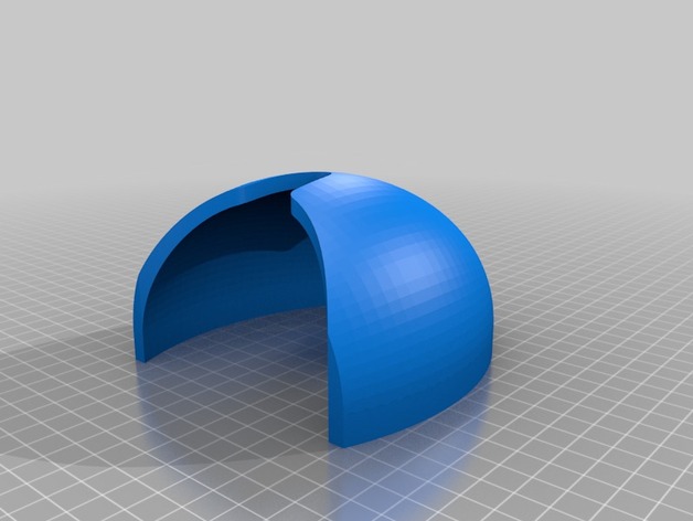
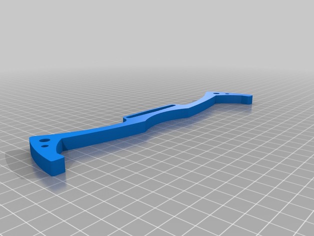
First, print all the parts of the PrintBot Crab using the 86Duino Enjoy (if you have any problems using the 86Duino Enjoy, please refer to this tutorial document ). When generating G-code using the slicing software, I found that two parts of the PrintBot Crab would exceed the printing range of the 86Duino Enjoy. These are the following two parts:
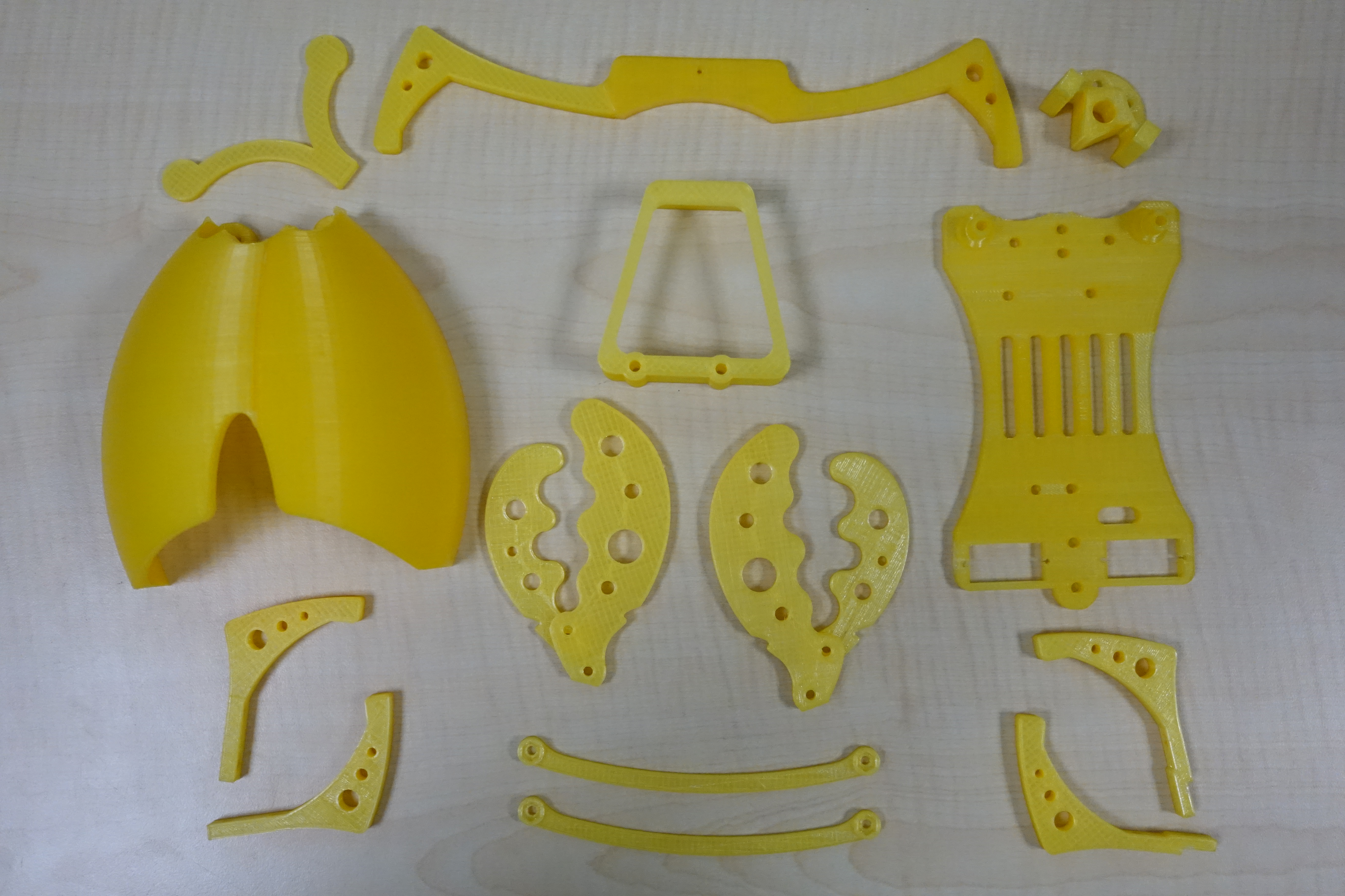
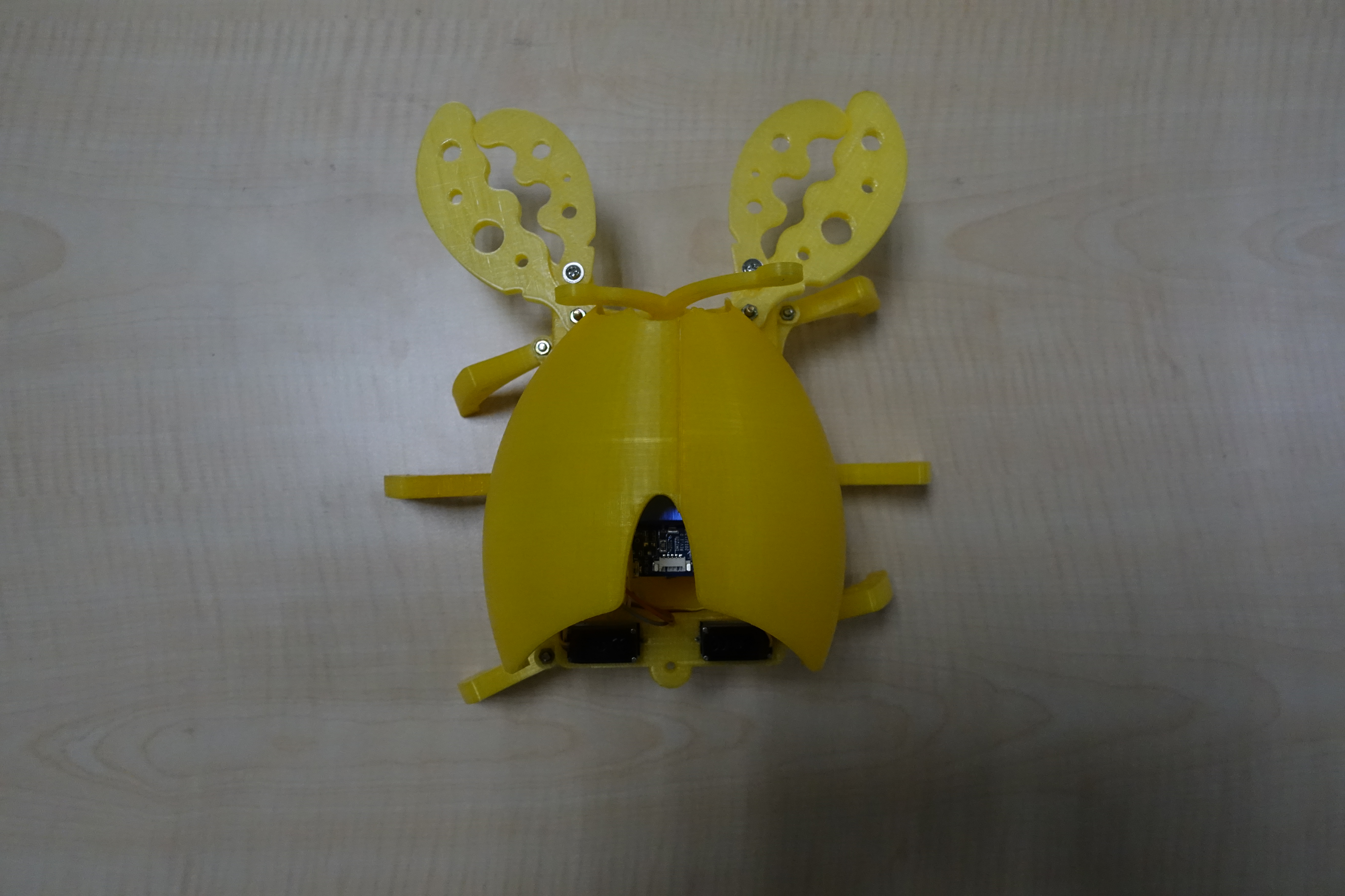
Use software that can edit STL files to split the two parts that exceed the printable area into two halves. Once split, they will no longer exceed the 86Duino Enjoy's printable area. If necessary, you can Download it here. The image below shows all the printed parts. The parts I disassembled for printing have been glued together using instant glue:
In addition to the printed parts, you'll need to prepare other parts to assemble the PrintBot Crab. The parts used here are not exactly the same as those used in the PrintBot Crab project.
— Screws —
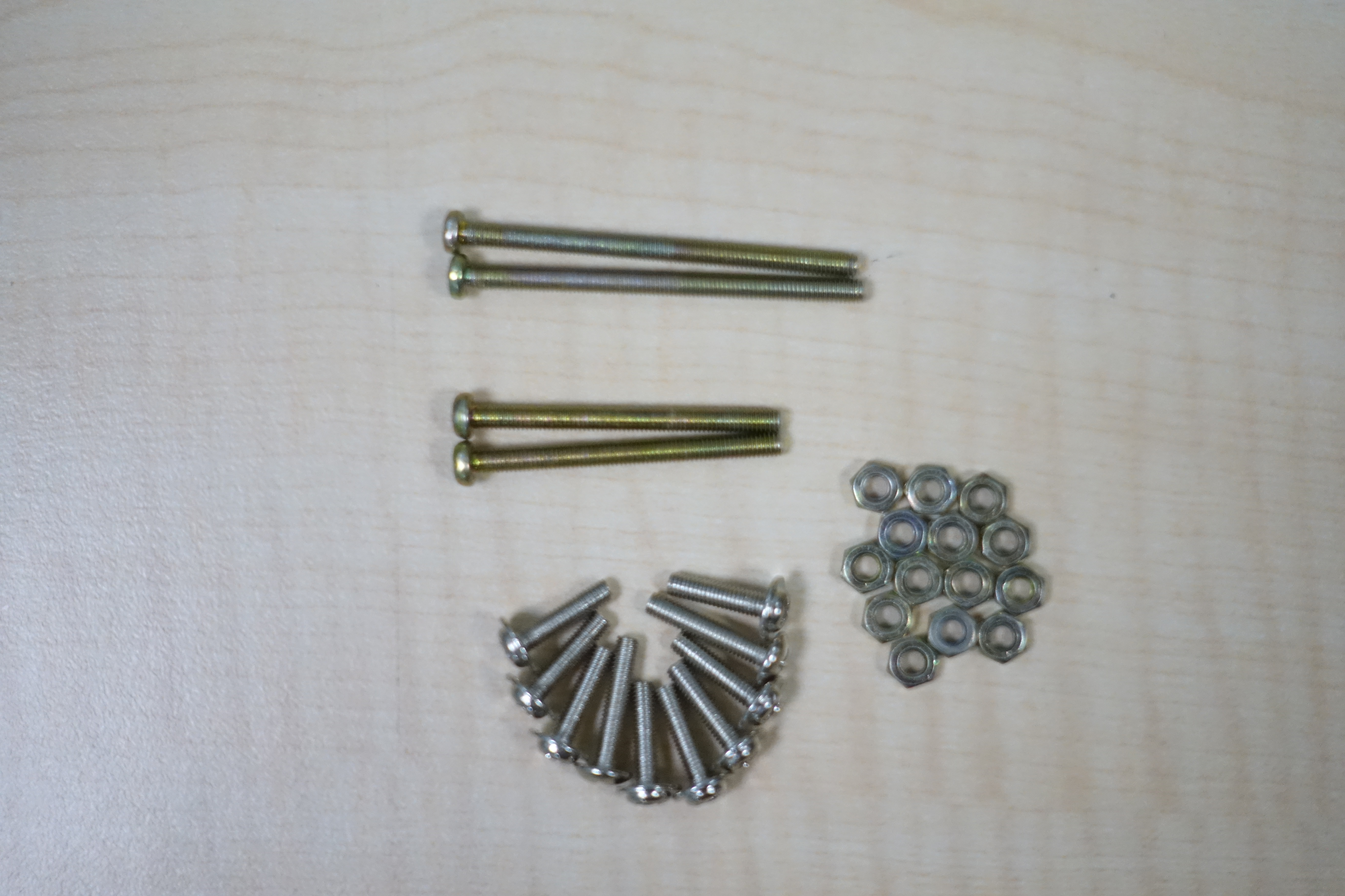
I'm using existing screws and nuts here, so the specifications are different from the original author's. The original author's screw specifications are listed in the assembly file for GUIA_Printbot_Cangrejo.
—Servo—
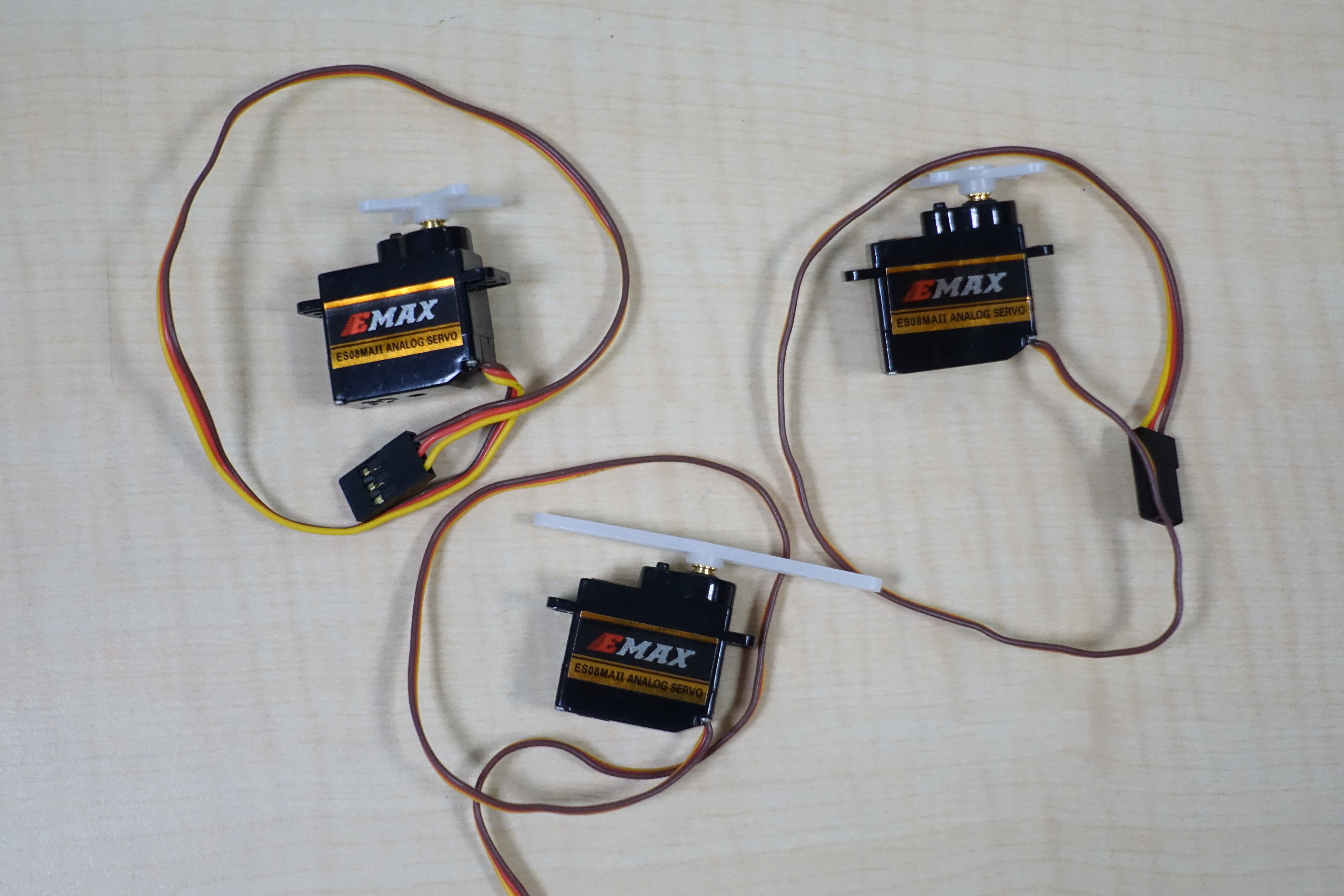
The servo uses an EMAX ES08MAII, which operates at a voltage of 4.8V to 6V.
— Battery —
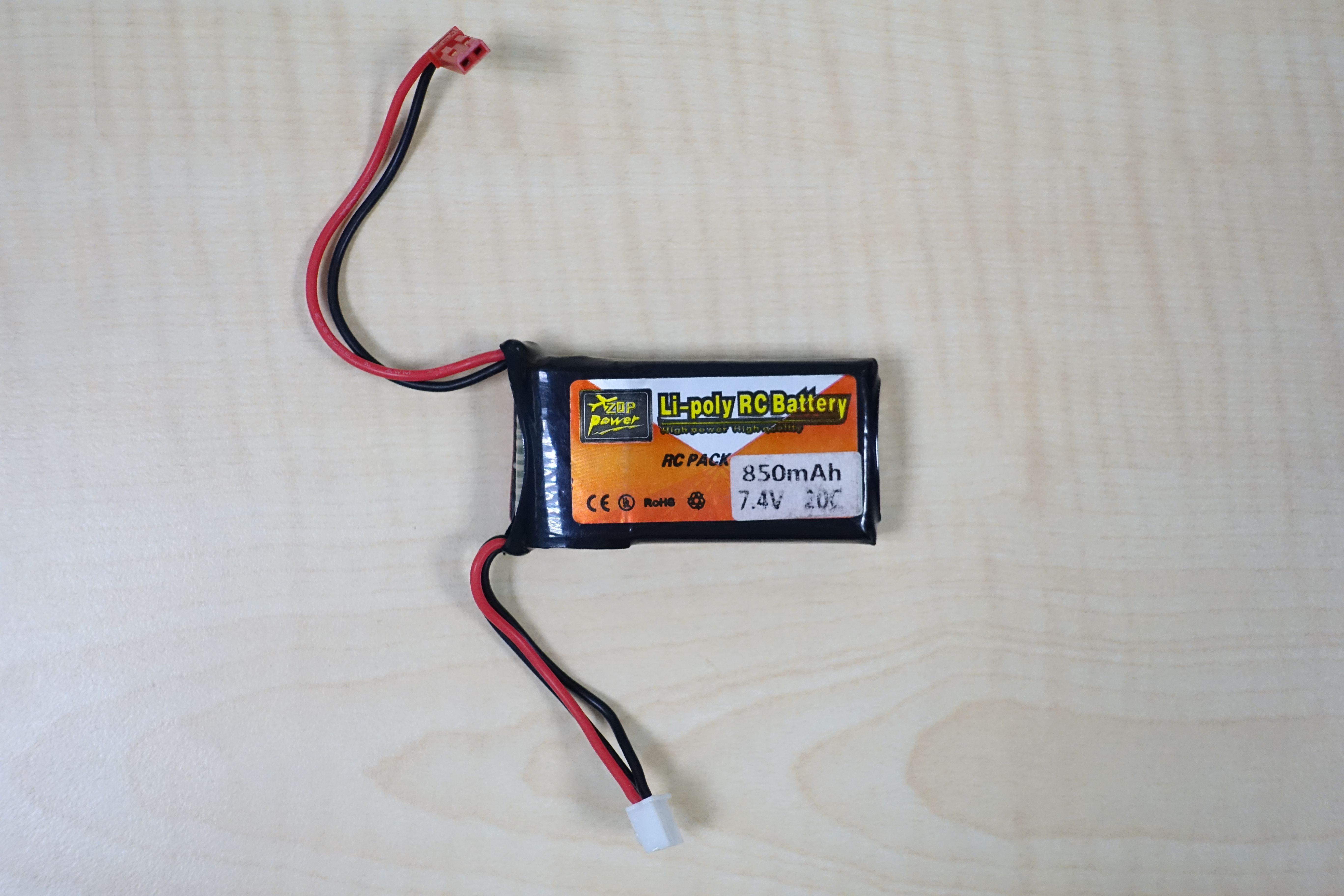
For the battery, choose a lithium battery. Be careful not to charge it beyond the servo's operating voltage, as this may damage the servo.
— Cables and Expansion Board —
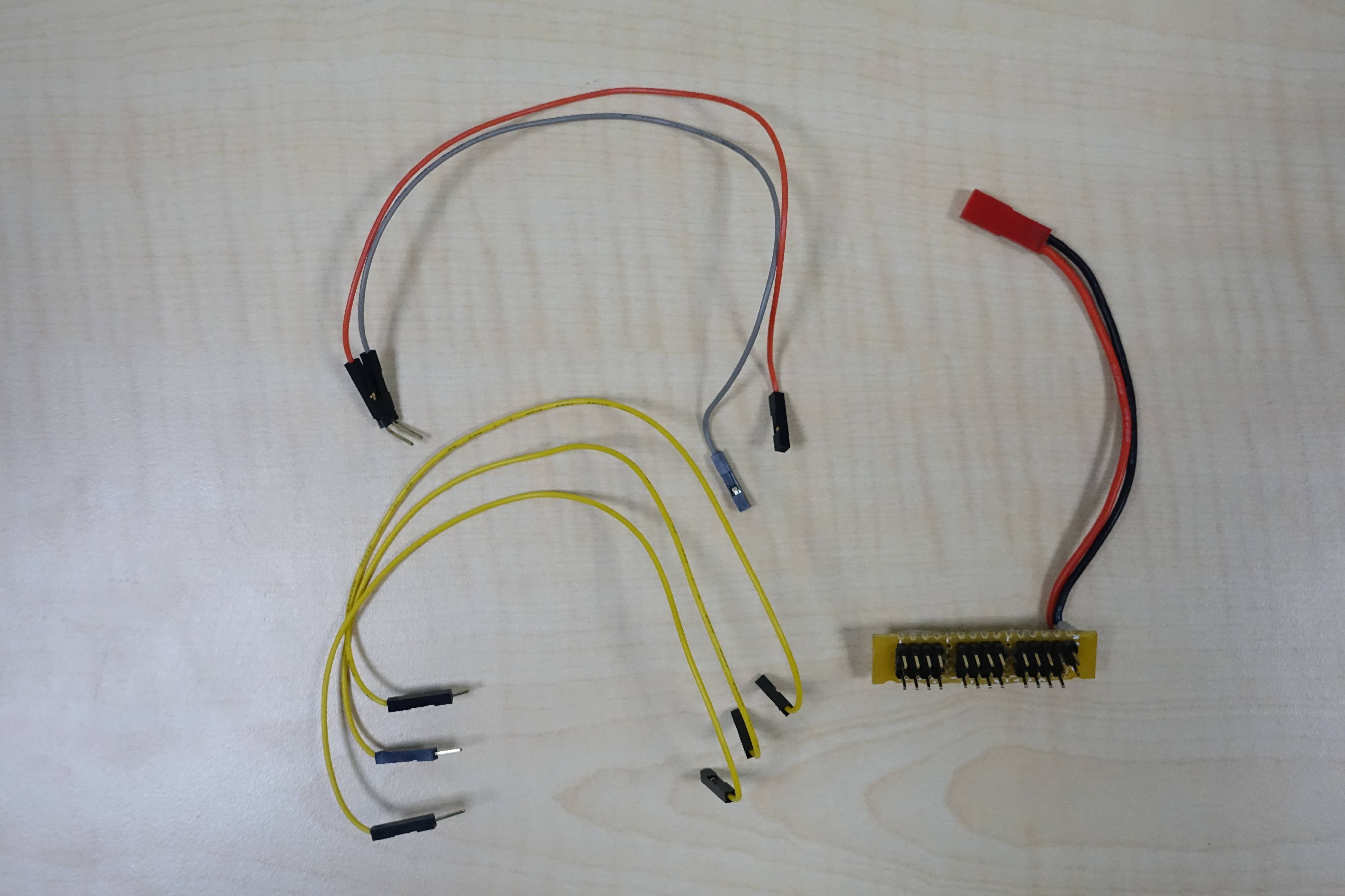
Prepare several Dupont cables for connecting the PWM signal and power supply, and make an expansion board (Click here for details) to facilitate connecting to the servo. 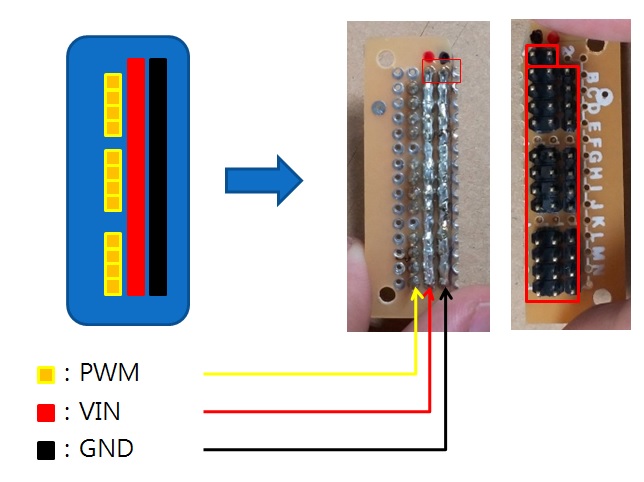
The top two pins on the expansion board are used to connect to the lithium battery. The positive and negative power pins can be seen on the back of the expansion board. The pins are connected in a row using solder. In addition to the power supply, there's another row at the top for connecting the PWM pins. Unlike the power supply, which is soldered together, each PWM pin is independent. With this expansion board, connecting a servo simply requires plugging the servo cable into the expansion board.
Hardware Setup
I won't explain every assembly step here. I'll only highlight some areas that require more attention or where the method differs from the original author's. For a more detailed assembly tutorial, please refer to GUIA_Printbot_Cangrejo.
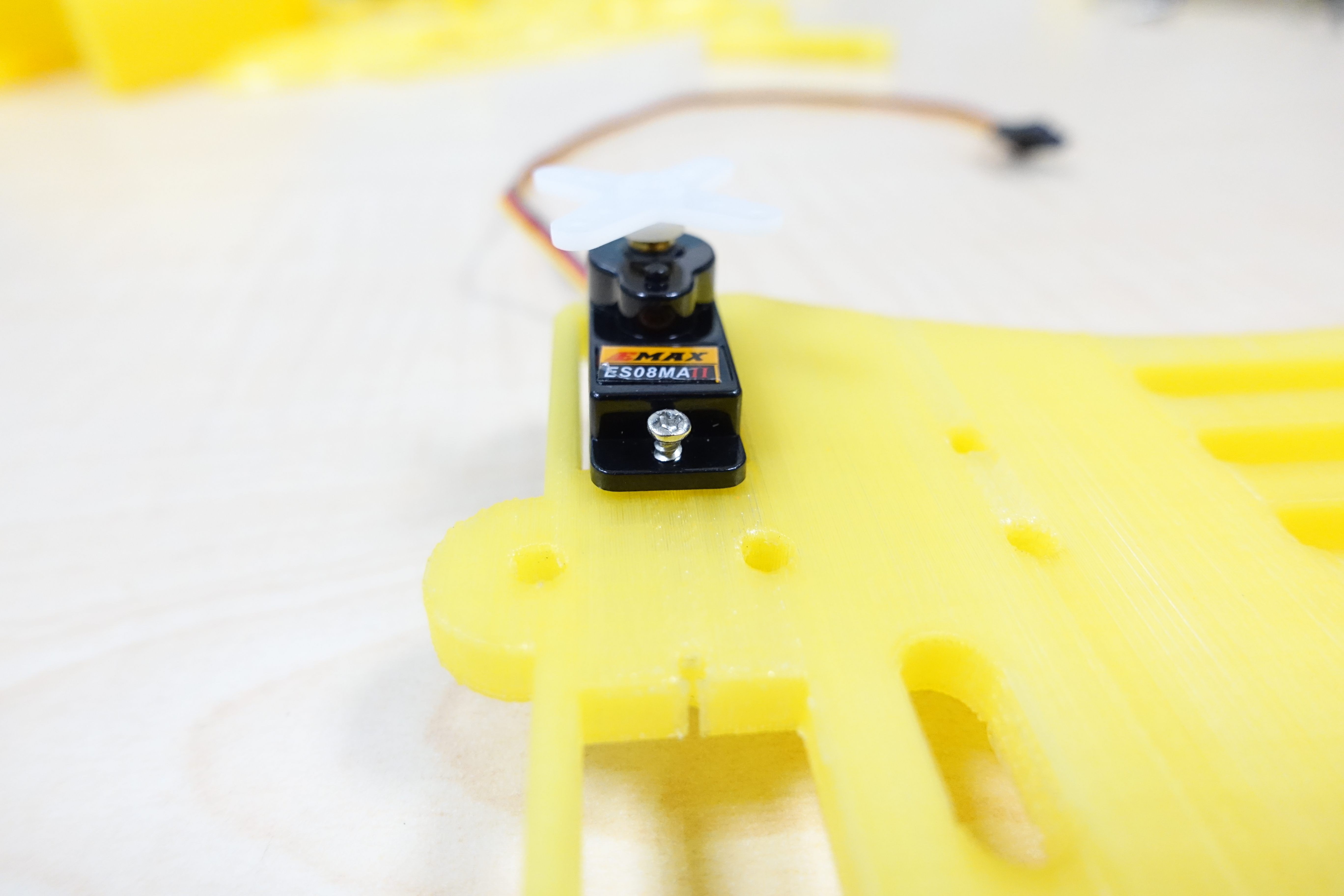
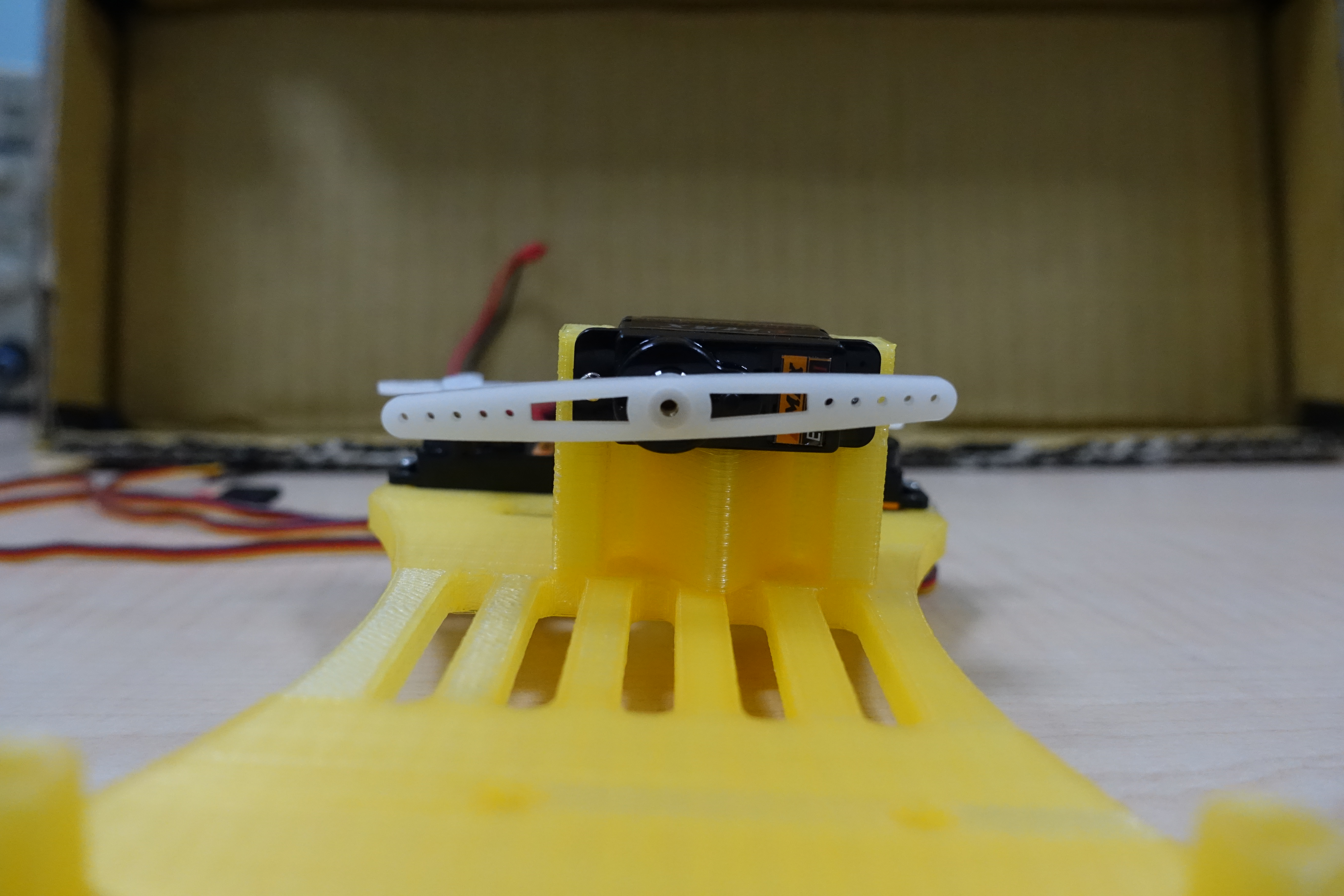
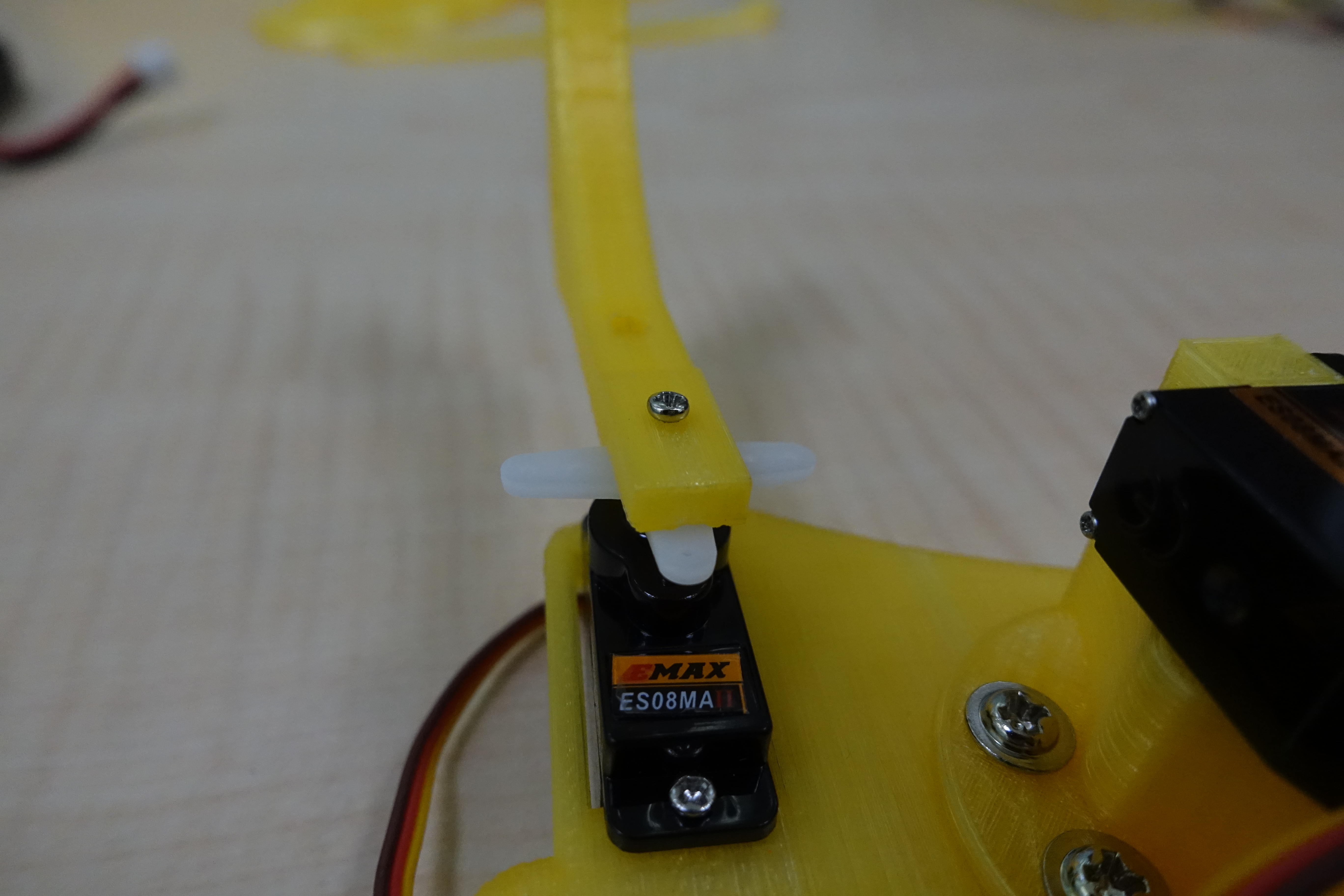
Installing the Servo
The screws used to secure the servo to the PrintBot Crab are included in the servo accessory kit.
Before attaching the turntable to the servo, you must first zero the servo. Zeroing means rotating the servo to the exact center of its range of motion. We use the Servo86 library to zero the servo. The following example code is provided:
|
1 |
|
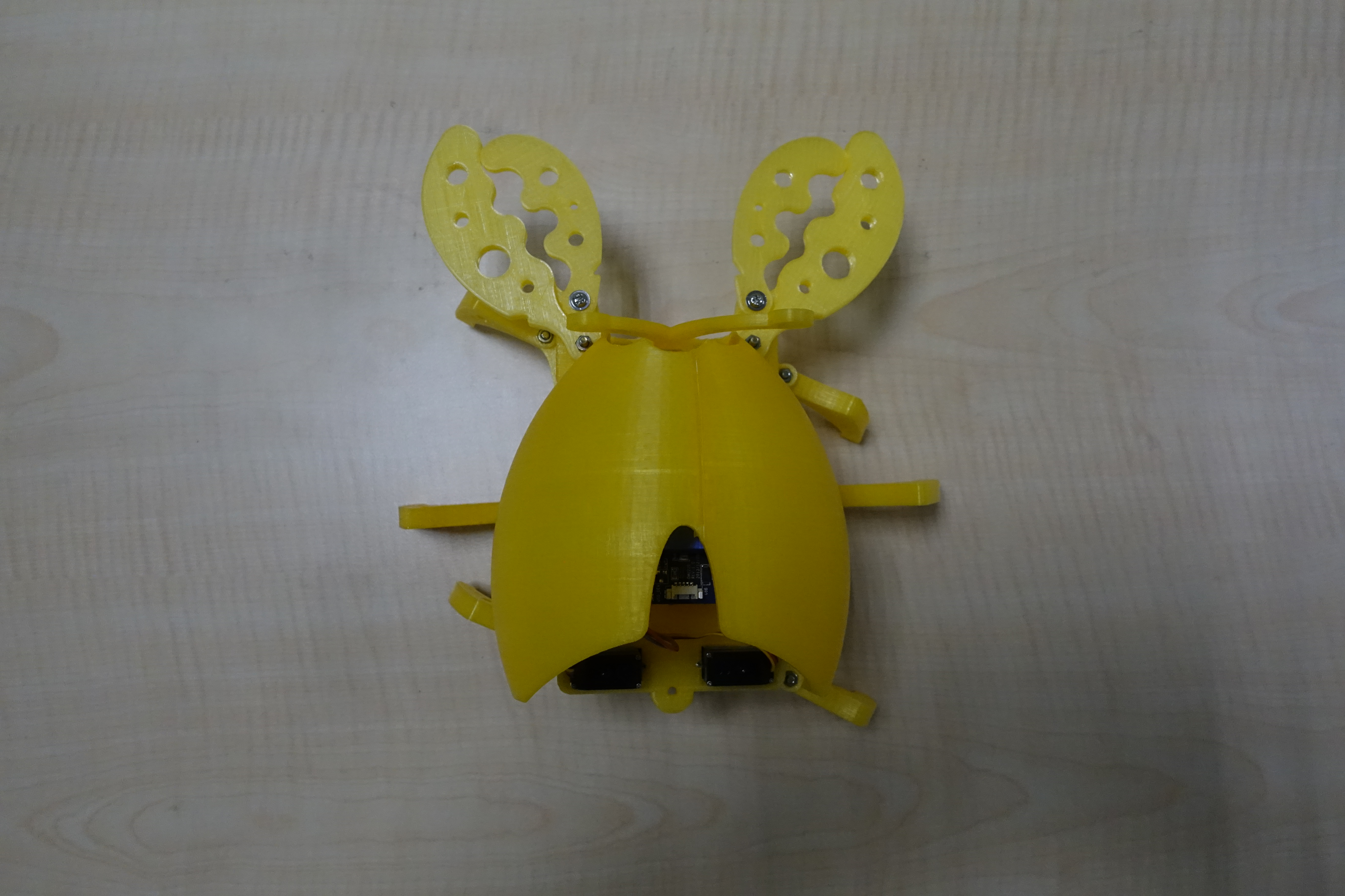
Only after the servo has returned to zero can we install the turntable on the servo. Sometimes the turntable cannot be installed perfectly to the position you want, but this does not affect it, because we can solve this problem later when editing the action. After all three turntables are installed, they should look like the image below: 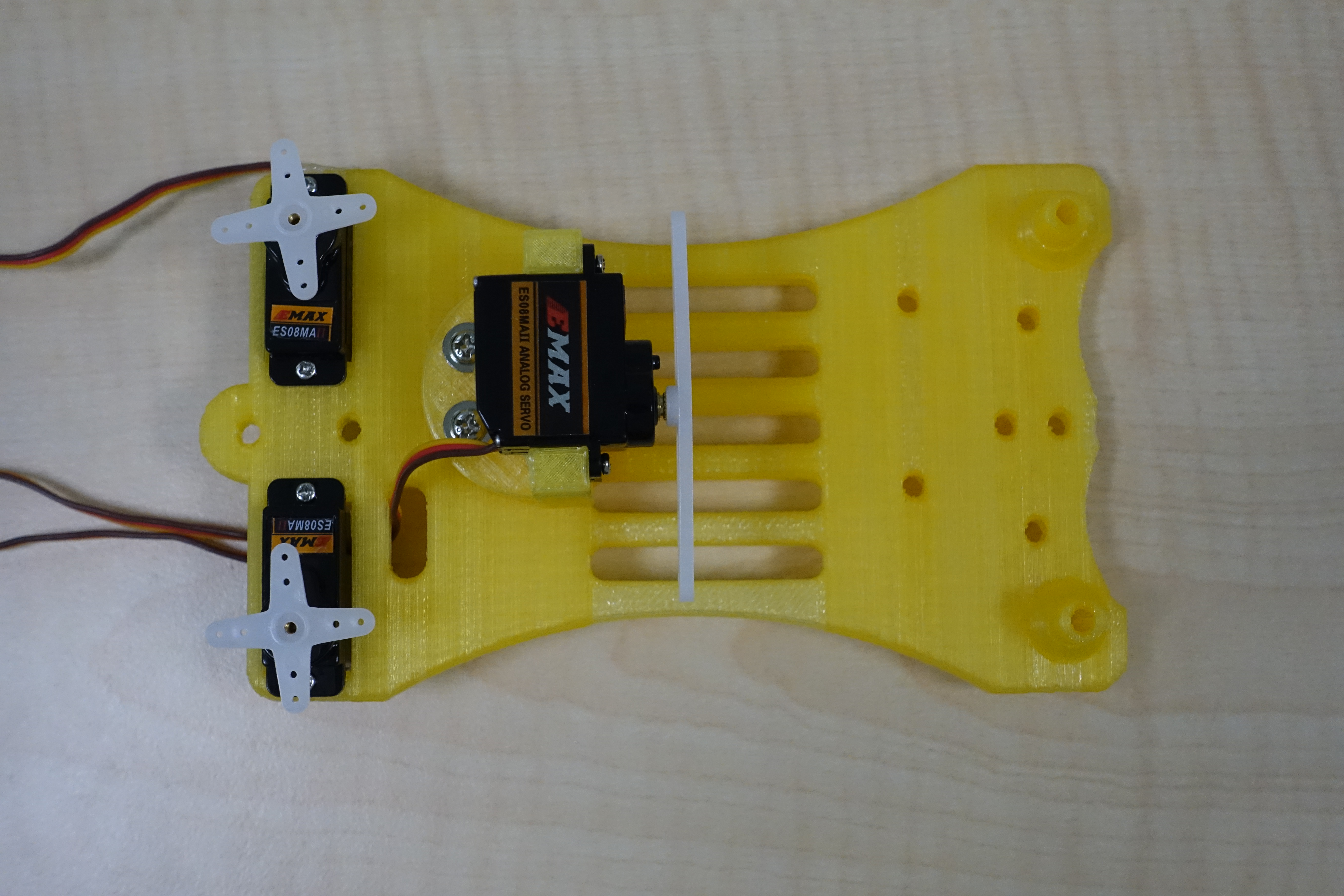
The screws used to secure the PrintBot Crab's printed material to the servo turntable can be found in the servo's accessory kit:
Connecting the Expansion Board
After securing the servo and 86Duino Zero to the PrintBot Crab, you can connect the 86Duino Zero, expansion board, and servo together. Let's take a look at the expansion board after it's connected:
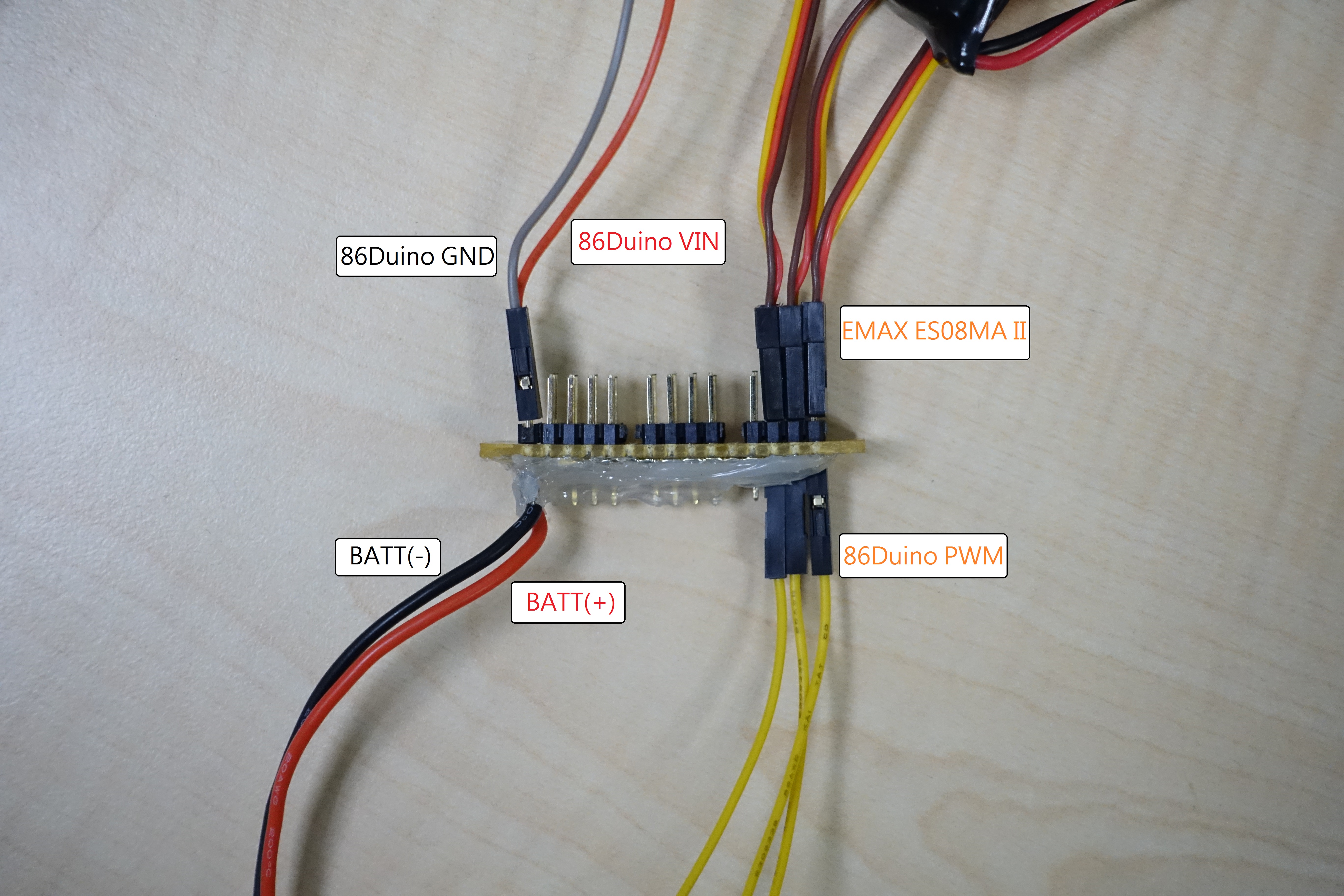
The 86Duino PWM wires marked in the image above need to be connected to the 86Duino Zero's PWM pins. The image below shows the completed 86Duino Zero:
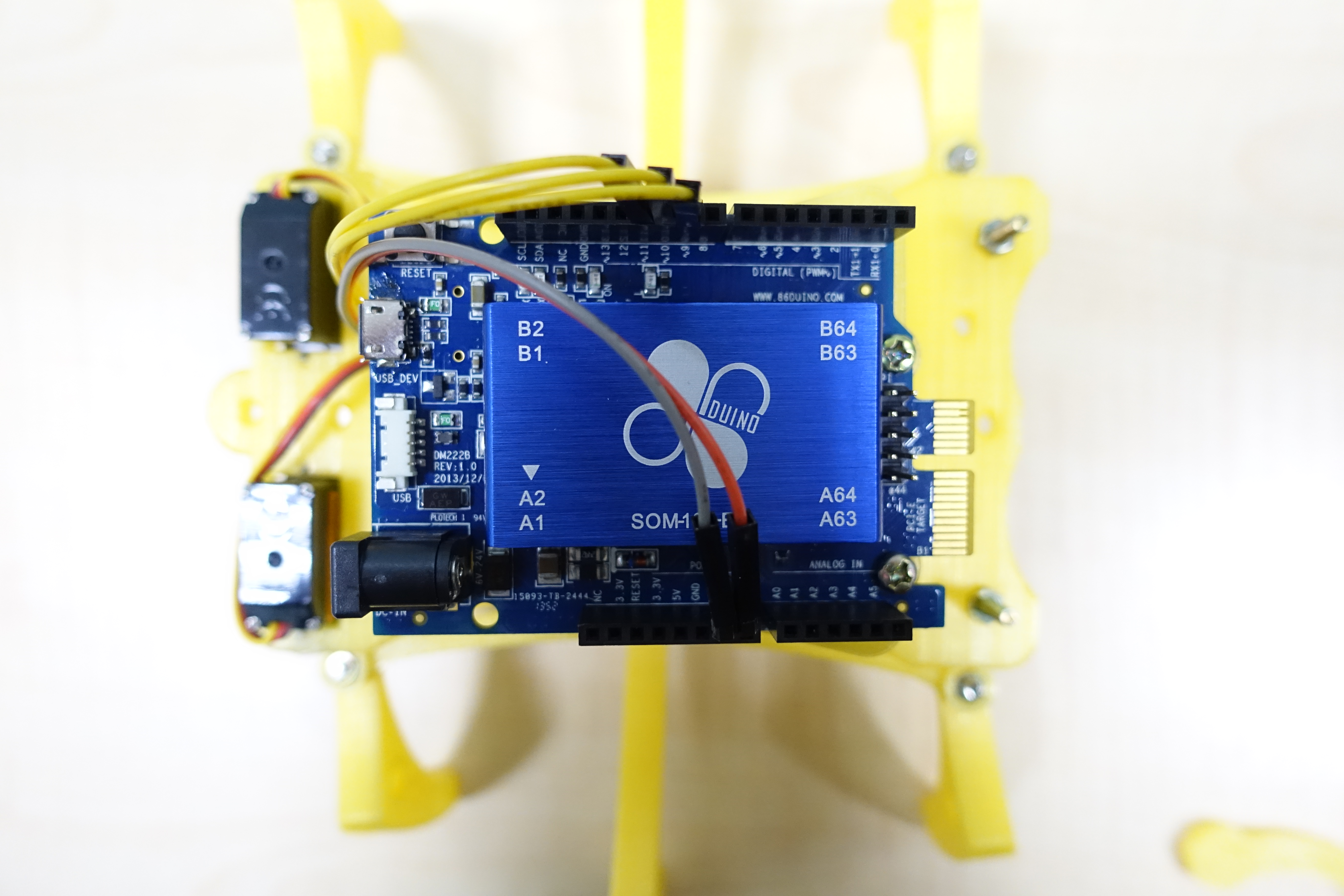
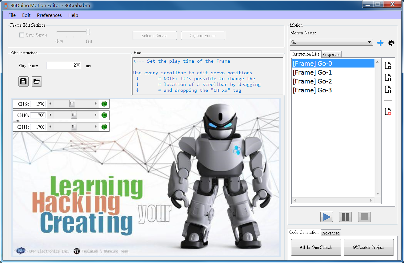
The PWM pins can be selected from any digital pins. Here, we select pins 9, 10, and 11.
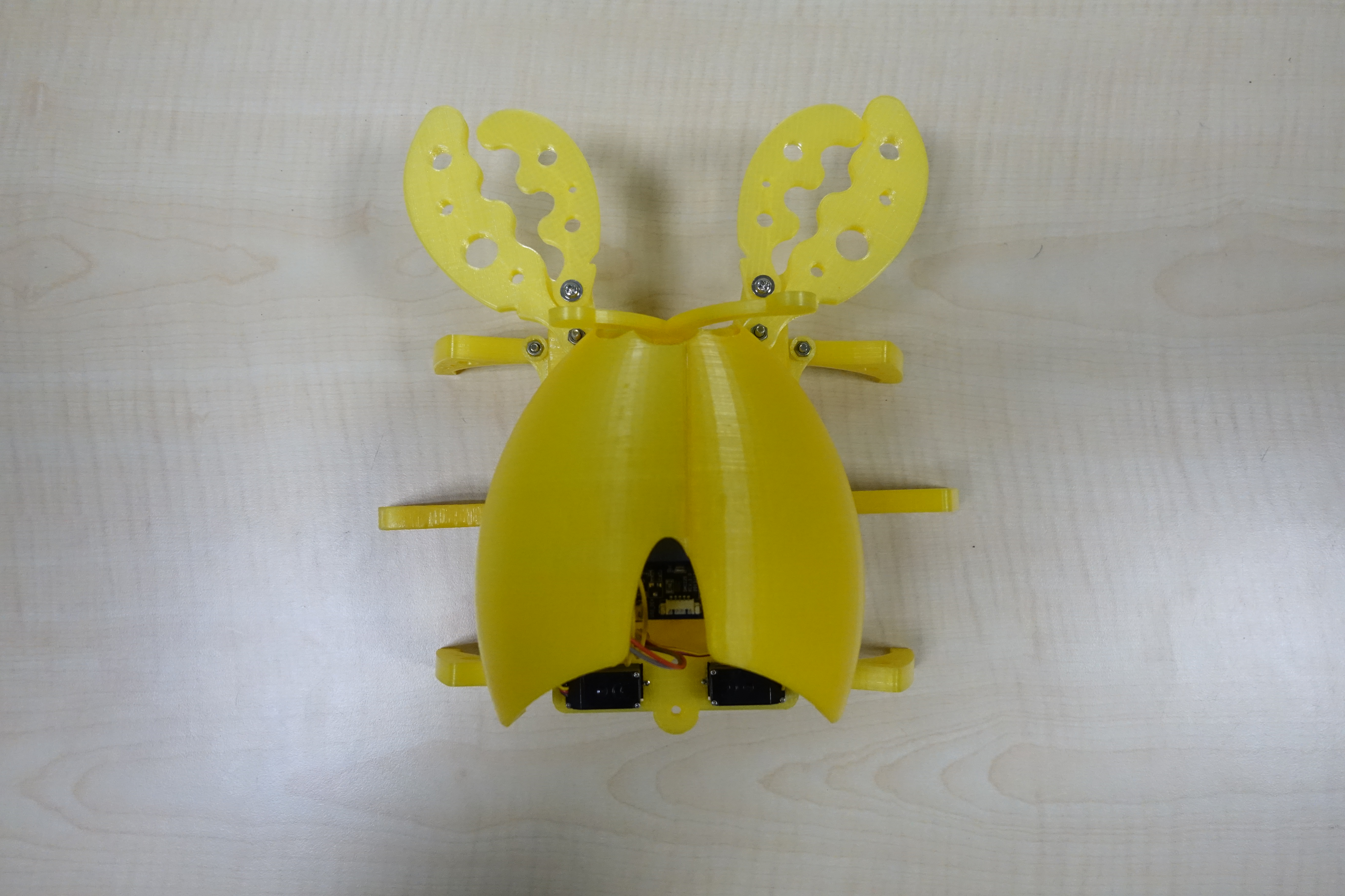
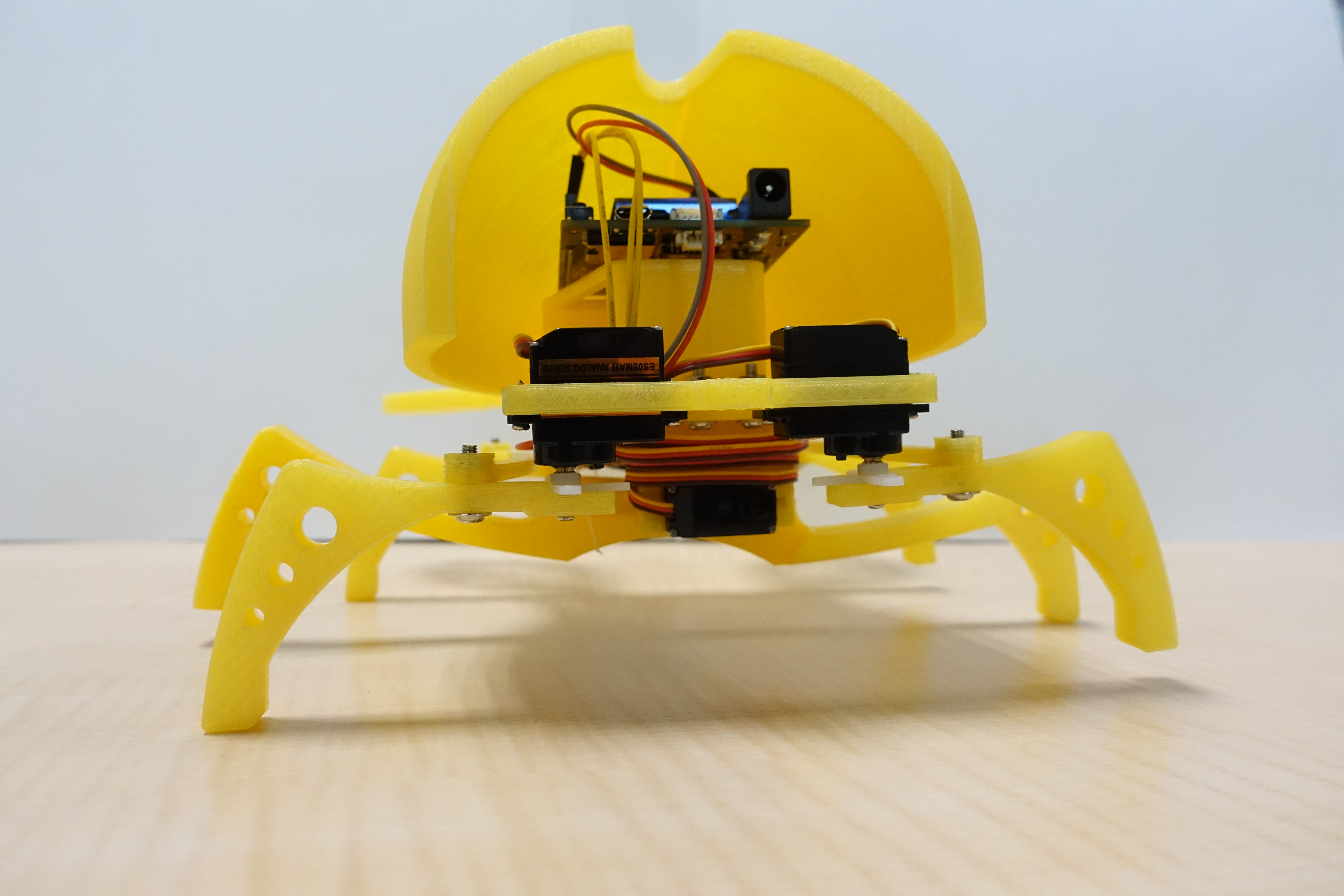
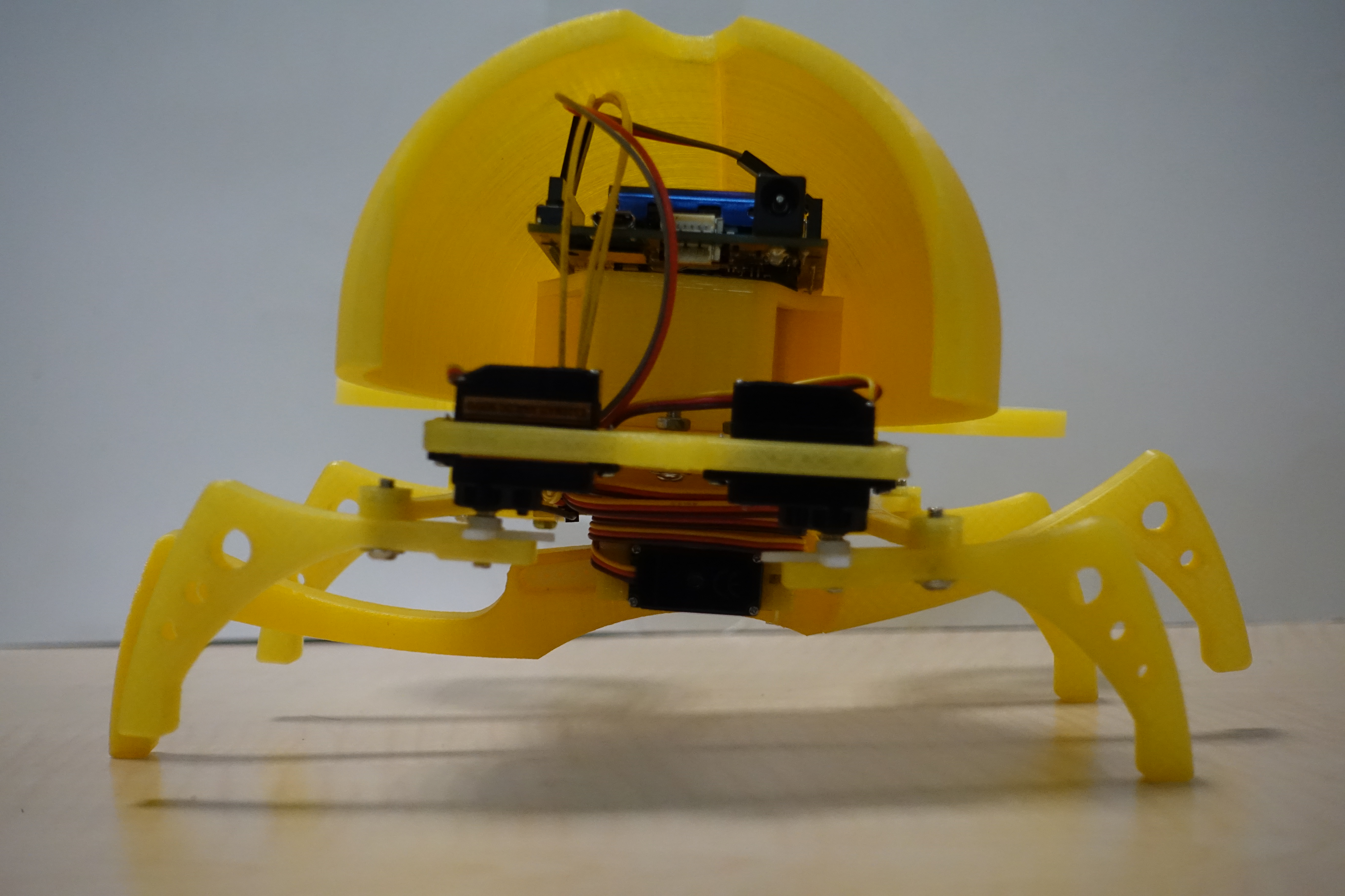
Finally, secure the expansion board. By attaching it to the bottom of the PrintBot Crab and properly aligning the wiring, you can create a perfectly organized appearance!
Gait Explanation
After assembling the PrintBot Crab, of course, you need to animate it. But before editing its movements, let's first learn how it moves.
Although the PrintBot Crab has six legs, it actually only uses three servos. The front right and rear right legs are controlled by one servo, the front left and rear left legs by one servo, and the center right and left legs by one servo. We need to control these three servos to control the six legs. For ease of explanation, we'll divide the six legs into three groups: the front right and rear right legs are called the "right legs," the front left and rear left legs are called the "left legs," and the center right and center left legs are called the "center legs." Next, we'll explain how the PrintBot Crab moves step by step:
1. Zeroing: Start with the PrintBot Crab's legs at the starting position.
2. Lifting the Right Side: Rotate the center leg downward and to the right, supporting the right side of the body.
3. Right forward, left backward: Move your right foot forward and your left foot backward.
4. Left Lift: Rotate your middle foot downward and to the left, supporting the left side of your body.
5. Right Back, Left Forward: Move your right foot backward and your left foot forward.
Then just repeat 2->3->4->5->2->3->…, and the PrintBot Crab will keep moving forward, never looking back!
Motion Editing
Now that we understand how the PrintBot Crab moves, we can use 86ME to edit its motions and bring it to life! This section provides the settings used in this project. You can use them as a reference and further adjust them to your desired settings. If you encounter difficulties using the 86ME, please refer to the 86ME User's Guide.
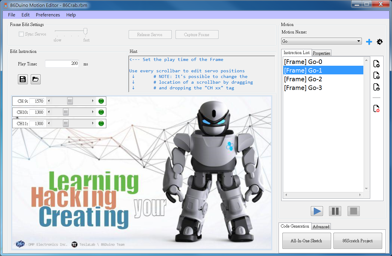
To make the PrintBot Crab move forward, we need to create a motion. This motion will contain four frames, corresponding to steps 2, 3, 4, and 5 mentioned in the previous section. Repeating this motion will cause the PrintBot Crab to move forward.
1. Raise the right side.
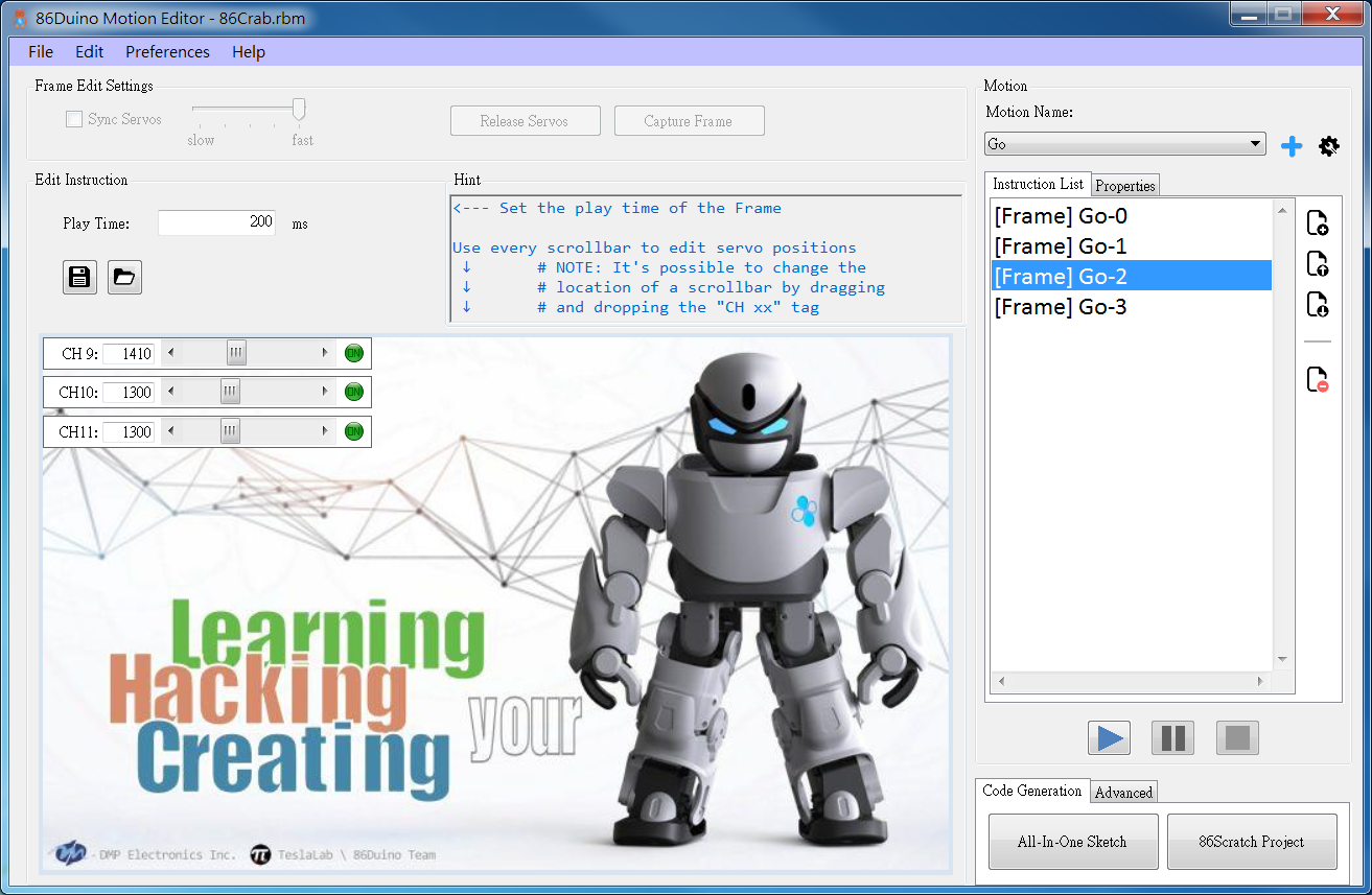
2. Right forward, left backward.
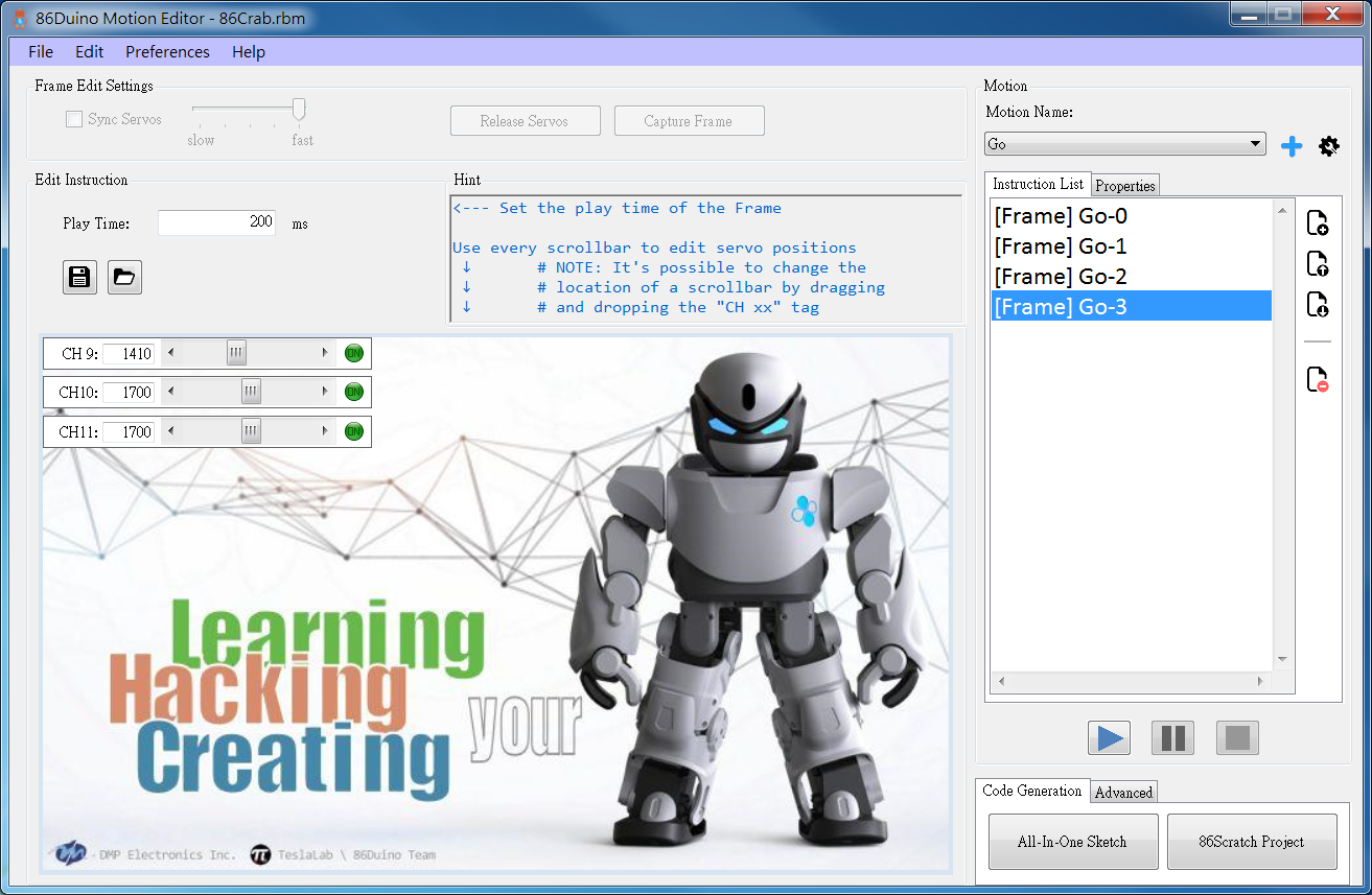
3. Lift the left side.
4. Go back right and go forward left.
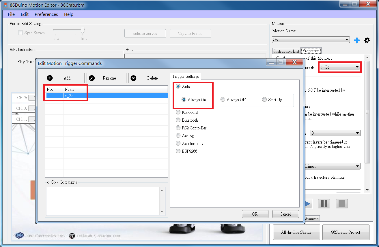
5.Finally, don't forget to set the trigger command to always on.
After editing the action, you'll create an All-In-One Sketch. Compile it using the 86Duino IDE and upload it to the 86Duino Zero. Connect the battery, and your PrintBot Crab will start moving!
Here's the edited 86ME file for your reference.
Achievement Display
— DEMO影片 —
Related Links
[1] This project Github
[2] This project STL structure file
[4] The useless little six-legged robot DIY course slides:
DIY course for the useless little six-legged robot DIY Courses from roboard
The text of the 86Duino reference is licensed under a Creative Commons Attribution-ShareAlike 3.0 License. Code samples in the reference are released into the public domain.