86Duino Motion Editor v1.95
86Duino Motion Editor (86ME) supports 86Duino development board to edit robot motion, making the process of editing robot motion faster, and can automatically generate 86Duino program for robot operation and editing motion.
86ME concept video:
Installation tutorial
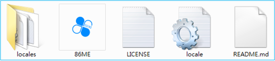
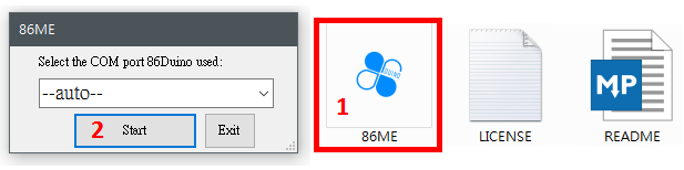
Currently 86ME supports Windows XP/Vista/7/8/10, and MicroSoft .NET framework 4.0 must be installed in the environment. Download 86ME and decompress it to get the folder 86ME. The files in it are shown in the figure below. They include the 86ME executable file, the required libraries and related instructions. In a supported environment, you can directly execute 86ME.exe to start operating 86ME.
Preparation
- Build a bridge between 86Duino and 86ME: 86ME will transmit commands to 86Duino through the Firmata library, so before using 86ME, you need to Burn the example draft of 86Duino Coding 210 (File->Examples->Servo86->MotionEditor) into 86Duino. After establishing the bridge of communication between the two parties, you can officially start to operate 86ME.
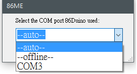
- Connection method and instructions: Currently, 86ME supports the computer to connect to 86Duino via COM port and send motion signals. 86ME will let the user select the interface between 86Duino and the computer at the beginning, and it is divided into three modes: automatic, offline, and selected to initialize the connection. Before executing 86ME.exe, you must first understand these modes. The –auto– option in the figure will open the last added COM port, COM4 is the COM port that 86ME detects on the current computer, and the –offline– option means offline mode, which will not communicate with 86Duino.
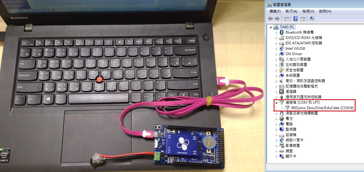
Therefore, offline mode only supports file editing and 86Duino program generation, and does not support real-time motor control. If you want to directly control the motor to edit the action, you must first connect the USB device on the 86Duino to the USB of the computer and select the COM port to which the 86Duino is connected (you can use automatic or select a known COM port). If you want to confirm which port the 86Duino is connected to, you can try to find the 86Duino and its connected COM port in the device manager. As shown in the example below, you can know that the 86Duino is connected to the computer's COM4. If you select the automatic mode without connecting the 86Duino, the program will switch back to the offline mode during execution.
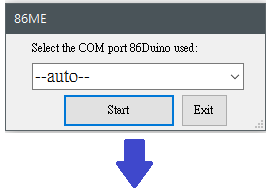
Generally speaking, offline mode is more suitable for users who are already very familiar with the robot's movements, allowing these users to easily edit existing files for adjustment. The Automatic Mode allows users to easily start using the 86ME, but if the computer is connected to many 86Duinos or many different COM ports, it is recommended to use the Selected Mode to avoid confusion. Then, after setting the COM port interface, you can press the Start button to enter the 86ME main window or press the Exit button to leave the 86ME.
Functional Description
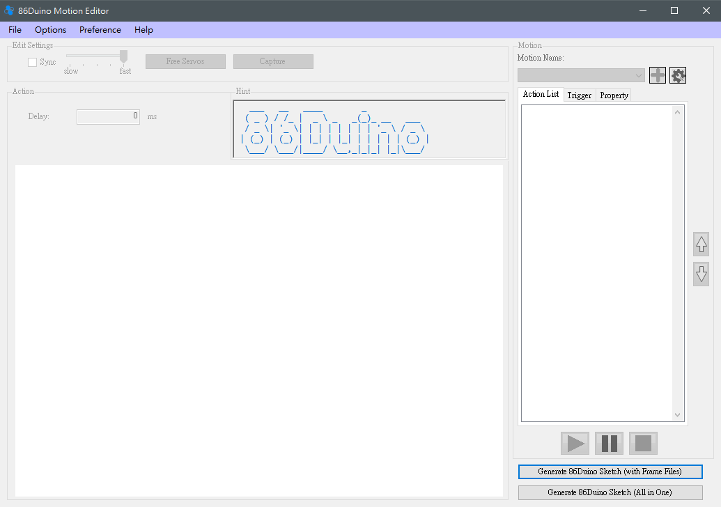
Here, we will first divide the program interface into several blocks for explanation. 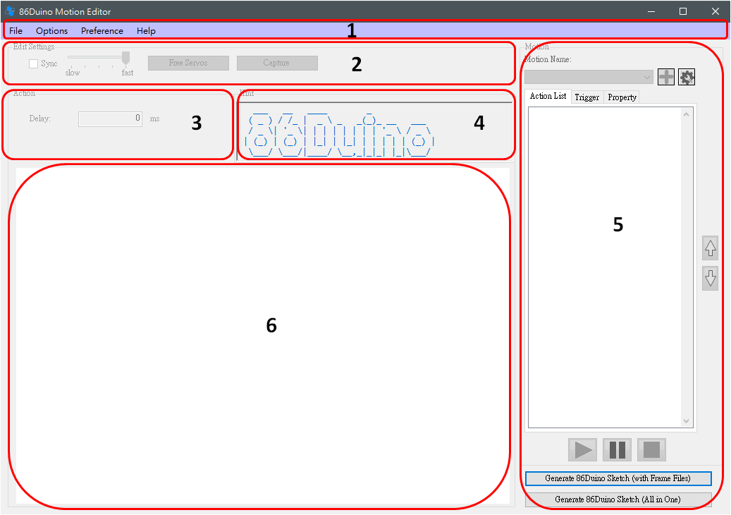
- This section has three drop-down menus File, Options, Help, and the expanded options are as follows
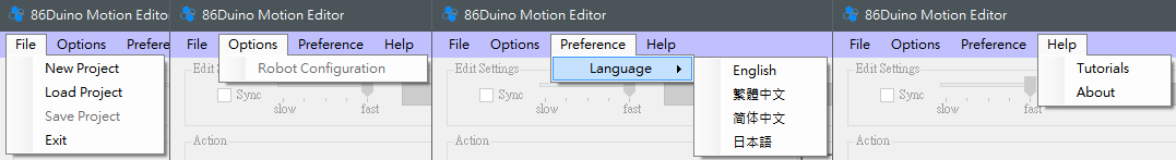
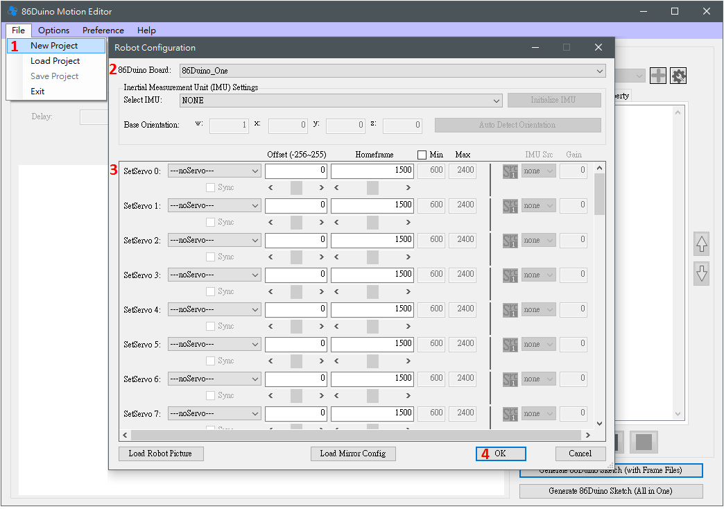
- File menu includes adding a new project, reading a project, saving a project, and ending a program. Sharp-eyed readers may find that many buttons are gray and unclickable at first. If you want to edit or test an action, you need to create a project using File->New Project or read a previously saved project using File->Open Project. File->Save Project can save the currently edited project, and File->Exit can end the program. So how do you add a new project? Clicking File->New Project will pop up a Robot Configuration window, in which you can set four robot-related settings.
(1) 86Duino Board: Used to select the 86Duino model used by the robot. Currently, there are 86Duino One/Zero/EduCake for users to choose from. Selecting different 86Duino models will open different numbers of SetServo for users to set. For example, 86Duino One has 45 pins that can control motors, so SetServo 0~44 will appear, while 86Duino Zero will only appear SetServo 0~13 and 42~44. 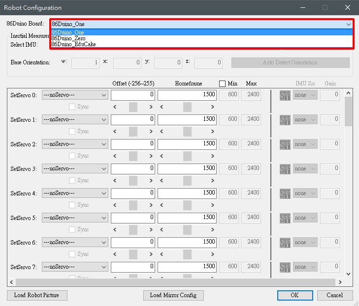
(2) IMU Settings: Set the Inertial Measurement Unit (IMU) used by the robot. Currently supported IMU models include the built-in IMU on the 86Duino One and the RM-G146. When you select an IMU model and are in connection mode, you can use the "Initialize IMU" button to initialize the IMU connected to the 86Duino, and you can use the "Auto Detect Orientation" button to detect the current IMU's Base Orientation. Only after these settings are completed can IMU compensation be used correctly.function to facilitate the robot's balance. 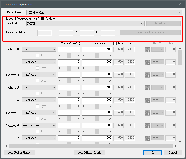
(3) SetServo: Used to set the motor connected to 86Duino. Here, the motor model, offset, home frame, maximum value (Max) and minimum value (min) supported by the motor are provided for users to set. The currently supported motor models are as follows: 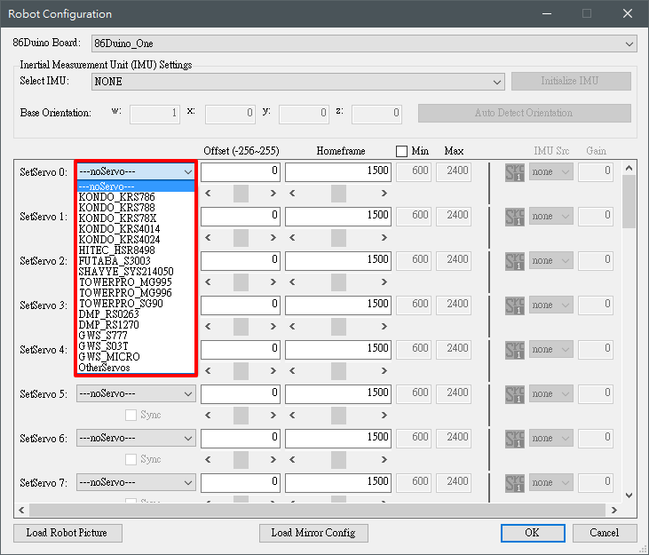 After selecting the motor, you can adjust the offset and starting position through the scroll control options in the figure below, and after checking the Sync control item, the angle of the offset and starting position can be synchronized with the motor, which can be adjusted in real time. The acceptable value range of the motor will automatically change after selecting the motor. If you want to modify it manually, you must first check the min Max control item in the upper right corner. If you have set up an IMU, you can set IMU Src to enable the IMU compensation function and select the compensation source. You can also set the compensation coefficient through the Gain field. If you want to add a second compensation source, you can click the Src 1 icon to switch to Src 2 to set the second compensation source.
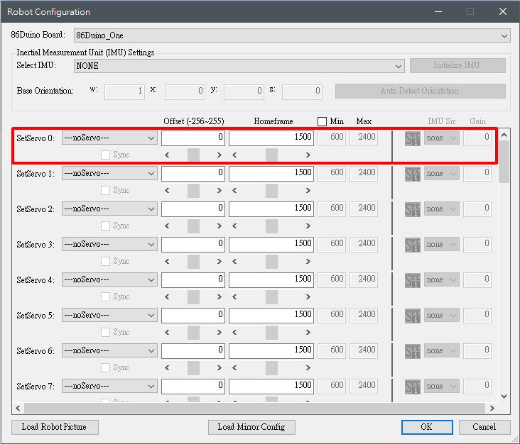
(4) Load Robot Picture: To facilitate the mapping of motor positions to various parts of the robot, the user can select a picture as a representative image of the robot. When editing the frame, the corresponding position of the servo and the picture can be selected to facilitate the user to identify the corresponding relationship between the servo and the actual robot. (5) Load Mirror Config: This function can read the user-defined mirror configuration, which is used to facilitate editing of robots with symmetrical relationships, such as humanoid robots. When the left half of the action is edited, this function can be used to copy the left half of the action to the right half of the action, speeding up the action editing process. The mirror configuration is stored in a file with the extension cfg. The content indicates the one-to-one correspondence between the servos. Each line contains a set of correspondences, separated by a "-" sign. For example, 1-2 means that the servos on pins 1 and 2 are symmetrical sides, 1 represents the left, 2 represents the right, and so on.
- Options menu contains the Robot Configuration option, which is used to edit the current robot-related settings. The content included is the same as File->New Project.
- The
- Preference menu allows users to select the language of the operating interface. Currently, it supports English, Traditional Chinese, Simplified Chinese, and Japanese.
- The
- Help menu includes the options of Tutorials and About. Clicking Tutorials will jump to the 86ME documentation on the 86Duino website, while About will display information related to 86ME, such as the author information, 86Duino official fan page, etc.
- The Edit Settings block has the following functions
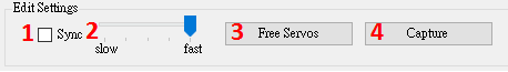
(1) The Sync function allows the user to decide whether to synchronize the currently selected Frame to be reflected on the robot immediately.
(2) The slot machine here can determine the speed of the motor during sync. There are five levels in total, with the right side being the fastest and the left side being the slowest.
(3) Release the motor so that it no longer outputs power.
(4) Capture is used to read the current angle of the motor. Currently, the supported motors are the Kondo, Hitec, and Futaba series. Please be careful when using it, because the Capture function will release all motors first. If the robot is not well supported, it may fall.
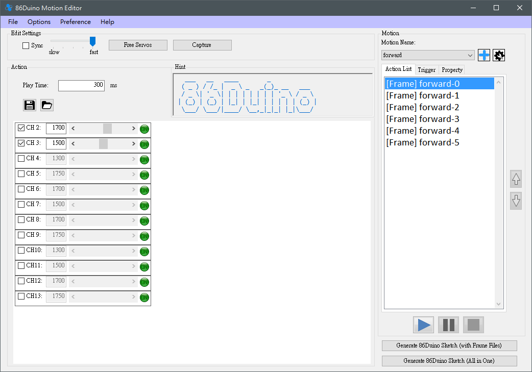
- Action block, can be used in
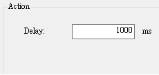
(1) Set the time to move to this action, in milliseconds.
(2) When the selected Action is Frame, two buttons will appear in the Action area: Save/Read 86Duino Frame File. The Save function can save the servo angle of the currently selected Frame to a text file, while the Read function can read the saved Frame File value to the current Frame.

- Hint block, in this block, some operation tips will be provided to users, such as how to add an action list, what precautions should be taken when executing an action, etc. If you are already very familiar with 86ME, you can operate the program according to your own ideas. The tips are basically for users who have just started using 86ME to provide the next step.
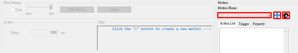
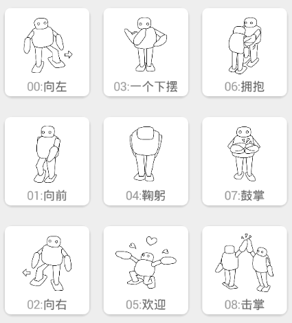
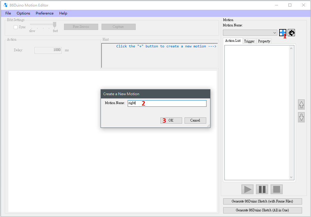
- Motion block, used to edit and test the robot's movements. Each action will be separated by "Motion Name". For example, users can add actions such as walking, punching, squatting, etc. Pressing the "+" button will pop up a window for users to determine the "Motion Name", as shown below:
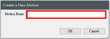
Press "OK" to add a new motion. To add another motion, press "+" and repeat the same process. To edit an existing motion, use the scroll bar in the "Motion Name" column. The gear-shaped button on the far right provides some functions for managing Motion, including copy, rename, delete, import and export.
Action List:
After creating Motion, you can start editing the action list (Action List). For example, if a certain action requires four frames to present, you can go to "Action List" Click the right button of the mouse to add an action.t/uploads/2015/04/86ME191_addaction.png">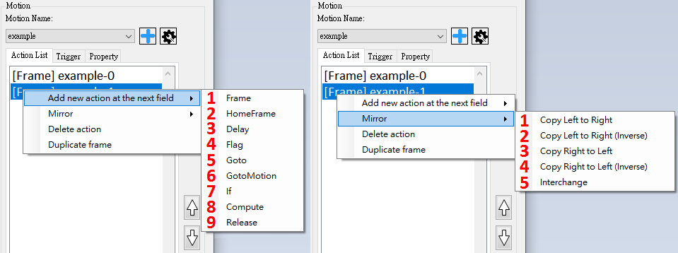
The main operations of Action List are
(1) Add Action, there are nine types of Action in total
(2) For the selected Frame Perform mirroring operations (as shown in the right picture above, a total of five operations), including mirroring (left to right and right to left, the left and right relationship is defined in the mirror file), mirroring with reverse values (relative to the servo home value), and left-right swapping.
(3) Delete the selected Action
(4) You can copy the Frame or HomeFrame to the next grid, and the up and down movement of actions can be completed using the two buttons below.
![]()
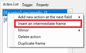
Action List also has a convenient function. When a Frame is followed by a Frame, a function will be enabled to insert a Frame. The angle of each motor is the result of adding the corresponding motors of the two frames before and after and dividing by two. This function can be used to easily edit the action between two frames with a large moving distance. The adjustment of action parameters will be explained in block 6 and the usage example.
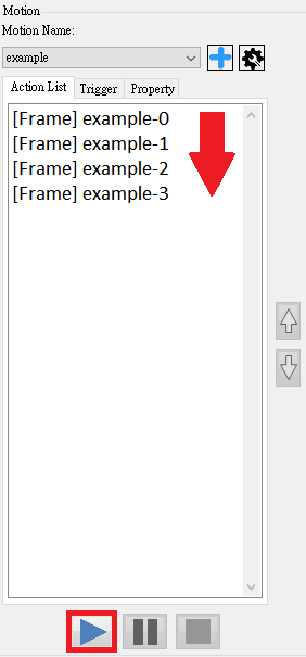
After editing the action list, if it is connected to 86Duino, press the play button to test the action from the first action to the last action in the Action List. Users can test the action through this function.
Trigger:
As for the two buttons at the bottom, they will output the current project into an ino program file that can be burned into 86Duino. Generate 86Duino Sketch (with Frame Files) will generate an ino file and several action setting files, while Generate 86Duino Sketch (All in One) will write all settings into an ino program. The file is generated according to all the currently edited actions plus each action's respective Trigger and Property. Trigger To set the trigger mode, select a motion and go to the Trigger tab. Currently, there are five supported trigger modes: auto, keyboard, bluetooth, ps2 controller, and accelerometer.
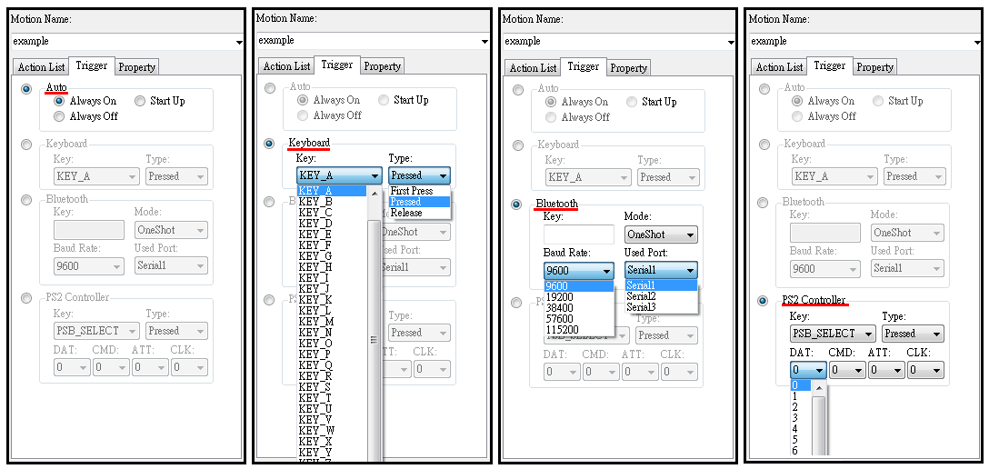 (1) Under Auto, there are Always On, Always Off, and Start Up. Indicates that this action will always be displayed, Always Off means that this action will never be displayed, and Start Up means that it will be displayed once when 86Duino starts up.
(2) Keyboard can set Key and Type. Key currently provides A~Z and up, down, left, right, blank, and ESC. Type provides First Press, Pressed, and Release. Motion will be triggered when the Key and the corresponding conditions are met. For example, the robot's walking is set to Key A, Pressed, and the robot's return to standing position is set to Key A, Release. When we press the A key, the robot will keep walking, and release the A key to return to standing. For more perfection, we can also add Key A, First Press as the starting step such as half-span.
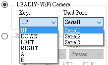
(3) Bluetooth can select a single-character Key input, as well as Mode and the Baud Rate and Serial Port where the Bluetooth module is located. For example, we assembled the Bluetooth module in the 86Duino Serial1, set the forward motion key to B. After generating and burning the program, you can use the mobile phone APP software (currently only supports single-character APP) to send signals to control the robot to move forward. The Mode options are OneShot and Continuous. The OneShot mode will trigger the action only once, which can be used for the robot to punch, kick, etc., while the Continuous mode will trigger the action continuously, which can be used for forward, backward, etc.
(4) PS2 Controller You can select the button on the PS2 joystick as the key, and set the type of triggering this button like the keyboard. In addition, if you want to use the PS2 joystick to control the robot, you must also set the four pins connecting the PS2 and 86Duino, namely DAT (data), CMD (command), ATT (attention), and CLK (clock). These four pins correspond to the 86Duino pins.
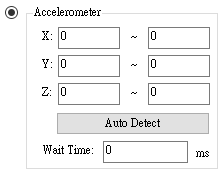
(5) Accelerometer You can select the accelerometer X, Y, and Z axis readings as the starting condition. Just set the range of the three axes and the time the readings remain in this range. The "Auto Detect" button is when the IMU is correctly in the Robot Configuration After being initialized, it can automatically detect the current accelerometer reading and automatically select a range to fill in the blank.
(6) 
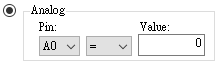
(7) Analog can trigger actions through analog signals, as shown in the figure below. Pin is used to set the analog source pin, the middle Combo Box is used to select the judgment condition, including =, ≠, ≧, ≦, >, <, and Value is used to select the value. When the condition is met, the action is triggered.
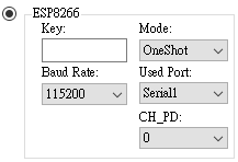
(8) ESP8266 trigger currently supports this APP. First, connect ESP8266 to 86Duino and set it to AP base station mode. Then set the corresponding Baud Rate, connected Serial Port and Which PIN of 86Duino is connected to the CH_PD pin of ESP8266? Then set the Key to correspond to the picture in the APP and you are done. The buttons in the APP are shown in the figure below. The Key value is the picture number plus "$PM". For example, the Key of the left button is "$PM00".
Finally, before compiling the generated program, you need to use the import library function in the Coding IDE to import the ESP8266 library. After successful compilation, the connection between ESP8266, 86Duino and APP is completed.
Property:
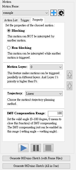
Property settings are currently divided into:
(1) Blocking and Non-Blocking: Blocking motion will not be interrupted by other motions in the generated program, while Non-Blocking motion will be interrupted by other motions.
(2) Motion Layer: Set the layer where the motion is located. This function allows motions of different layers to be triggered at the same time. For example, when a humanoid robot is moving, it can still trigger a punching motion. However, if two layers of motion use the same servo, there will be a priority issue. Here, the motion of layer 1 will be higher than that of layer 0. So when an action is set to Motion Layer 1, the user needs to check the servo to be used in the Frame properties, as shown in the figure below. In this way, when the actions of Layer 0 and Layer 1 are triggered at the same time, the selected servos CH 2 and CH 3 will prioritize the action edited by Layer 1.
(3) Trajectory: Set the method of motion trajectory planning. Currently, Linear and Constrained are supported. There are four planning methods: Cubic, Natural Cubic and Catmull-Rom Spline. The three Cubic planning methods can reduce the vibration generated during movement compared to Linear, and the Natural Cubic effect is the most significant. However, the Natural Cubic planning method may cause overshooting, that is, the curve of the action may become too large. The Catmull-Rom Spline and Constrained Cubic planning methods can avoid this problem. Among them, Constrained Cubic can best suppress overshooting, but the effect of reducing vibration is not as amazing as Natural Cubic. The three Cubic planning methods currently only support actions that are all Frames, that is, they cannot contain actions other than Frames. If there are other actions, they will automatically degenerate back to Linear. Please pay more attention when using them.
(4) IMU Compensation Range: Set the effective angle of the IMU compensation function (0~180 degrees, 0 means turning off the compensation function). Only within the (-set value ~ +set value) angle, the IMU The compensation value will be generated. This function can set the effective range of compensation. If some actions do not require compensation, you can also set it to 0 to turn off compensation.
The final generated program has two types, and the burning method is slightly different.
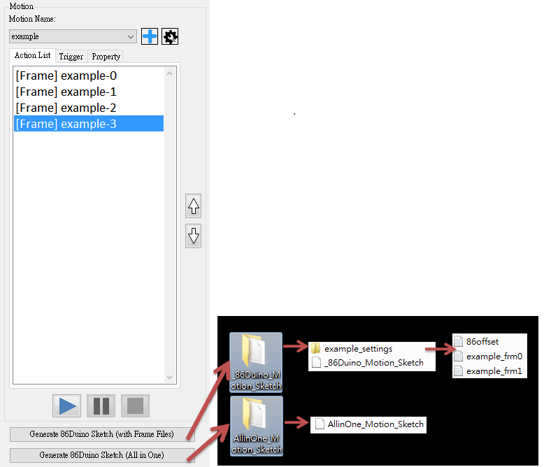
Generate 86Duino Sketch (with Frame Files) In addition to burning the ino program into the 86Duino In addition, you need to put the generated configuration file folder into the root directory of the 86Duino SD card (Make 86Duino SD Card) to run it correctly. Generate 86Duino Sketch (All in One) will only generate an ino program. Just burn the generated program into the 86Duino.
- This block is used to modify the details of each different action in the Action List, such as the angle of the motor in each Frame. To demonstrate how to operate in detail, a more complete usage example will be used below.
Usage Example
This usage example hopes to allow users to understand the operation process of 86ME. 86ME uses a hexapod robot composed of three servo motors as an example. This hexapod robot is composed of an 86Duino Zero and three DMP_RS0263 chips. The left, middle and right legs correspond to the 11th, 43rd and 44th pins of the 86Duino.

Step 1:
- Double-click 86ME.exe in the 86ME folder to execute it.
- Select –auto– to automatically connect to the COM port and press the Start button.
Step 2:
- Click New Project to add a new project, and then the Robot Configuration window will pop up.
- Set 86Duino Board to 86Duino Zero, which is the 86Duino model for this example. This example does not have an IMU, so it is set to None.
- Set pins 11, 43, and 44 to motor DMP_RS0263 servo motors. The offset, homeframe, Max&min here can be set according to user needs. This example uses the default values. IMU compensation is set to no compensation.
- Press the OK button to complete the setting.
Step 3:
- After creating the project, you can find that the “+” button lights up. We can use this button to add a new action. Press the “+” button
- The Create a New Motion window pops up. Enter the name of the action to be added in the Motion Name field. The example here is right (turn right)
- Press “OK” to complete the creation of the action
Step 4:
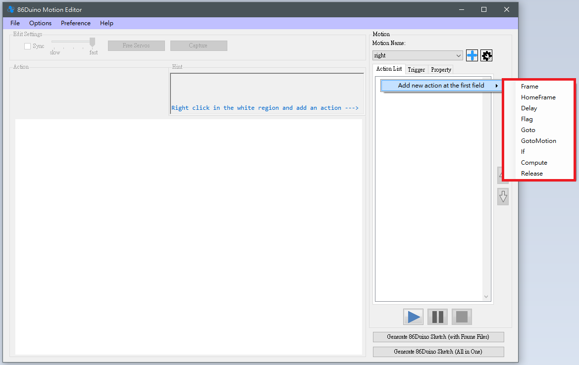
Right-click the blank space below the Action List -> add action at the first field to select an action to add to the action list.
There are nine types of Action, and their functions are described as follows.
Frame
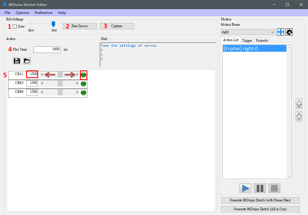
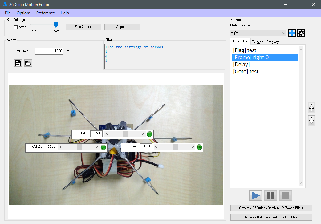
After selecting Frame, you can adjust the three motors that were originally set, and several functions will be enabled for users to adjust.
- Checking Sync will make the robot respond to the currently set value immediately. When Sync is checked, moving the scroll bar below or changing the number will make the robot respond immediately. The slot machine next to Sync can adjust the speed of the motor when Sync is on.
- The Free Motors button can release all motors in the output state and stop them from outputting.
- Capture is used to read the current motor angle. The motors currently supported are Kondo, Hitec, and Futaba series. Please be careful when using it, because the Capture function will release all motors first. If the robot is not supported well, it may fall.
- Play Time is the number of milliseconds it takes to move to the currently set motor angle. You can set it by directly entering a number. If it is set to 0, the action will be skipped, so please remember to set the Play Time.
- Set the PWM signal value to be sent to the motor. You can set it by scrolling or entering the value. There is a round button on the far right, which is used to individually determine whether the motor should be Synced. By default, all motors will rotate according to the given target PWM value when Synced, and will be displayed as green "ON". When this button is clicked, the image will turn into red "OFF" and the motor will stop outputting. This function can let the motor that does not need to be edited to rest, so as to avoid burning out due to long-term output.
Delay
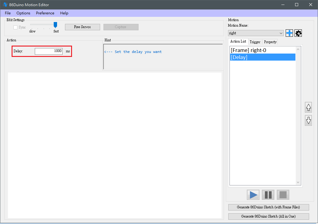
The user can set the Delay, and the delay here is a simple stagnation, which will not cause the robot to have any action.
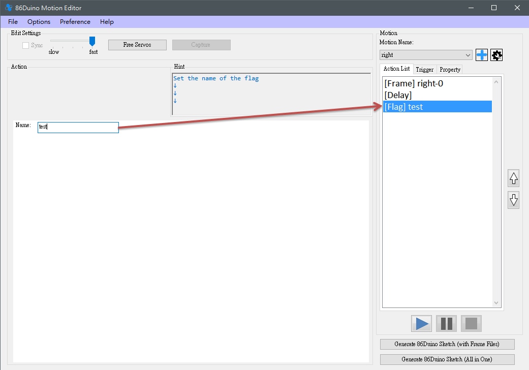
Flag & Goto
- Goto and Flag allow users to test actions in a loop without having to write a long string of frames. Flag only needs to be named, and then the flag in the Action List can be checked to see if the flag has the name just set. If so, the setting is successful.
- In addition to setting the name, Goto must also set the number of loops and whether to trigger and the number of Gotos, or you can choose to jump infinitely. The detailed behavior of Goto is that in the playback state, when executing to Goto, it will check whether to execute this Goto. If it is to be executed, it will look for the target Flag name set by Goto, and once found, it will start the action again from the Flag side.
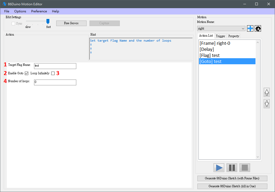
- Write the name of the target Flag. Write the same test as the Flag just created.
- Set whether to execute.
- Set whether to execute Goto infinitely.
- Set the number of executions.
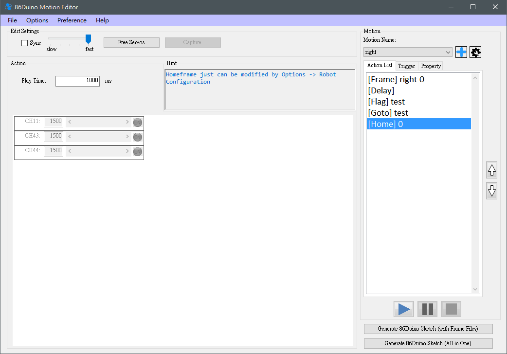
HomeFrame
Selecting HomeFrame will add a Frame with the value of the initial position and cannot be changed. To change the value of HomeFrame, you can only modify it in Options -> Robot Configuration. This option is convenient for users to return to the home state and can identify where the return to home action will be performed.
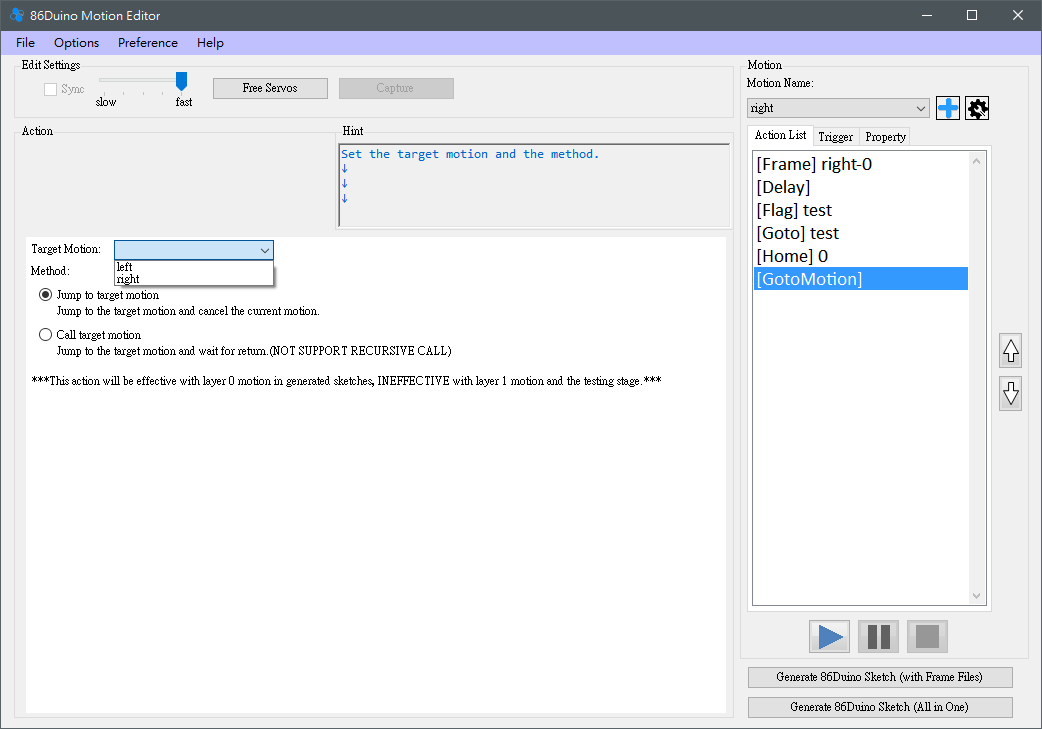
GotoMotion
GotoMotion can easily make the robot operate other Motion contents, just need to simply set the Target Motion and Method. GotoMotion will only be reflected in the generated program, and currently does not support the use of 86ME playback for testing.
- Target Motion: The motion to be executed. When selecting the target motion, please pay special attention to the fact that 86ME currently does not support recursive calls, such as calling itself or calling each other. These situations may cause unexpected actions to occur. Please pay special attention!
- Method: Divided into Call target motion and Jump to the target motion. Call target motion will continue to execute the remaining actions of the current motion after executing the target motion; Jump to the target motion will not return to the current motion.
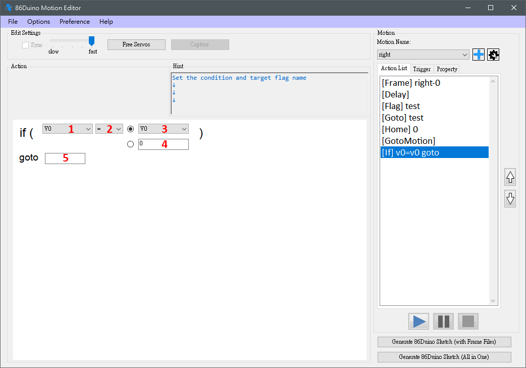
If
If provides flexibility in action editing. Currently, it provides 50 variables and several practical system variables for users to use. Just set the judgment condition to be met, and it will Goto to the specified Flag.
- Set the variables of the left sub-formula, "V0~V49" are variables that users can use. It should be noted that these variables are shared by all actions. Other system variables include "NowTime" which indicates the current time of 86Duino (ms), "Random" which indicates a random number, "Analog0~Analog5&Prime" which indicates the readings of A0~A5 on 86Duino, "AccX/Y/Z" which indicates the readings of the accelerometer's X, Y, and Z axes, "GyroRoll" and "GyroPitch" which indicate the current IMU's inclination angle relative to the Base Orientation. Roll corresponds to the X axis, and Pitch corresponds to the Y axis. "VKeyUp" and "VKeyDown" are virtual buttons. When the button is not pressed, the value is 0. When it is pressed, the value is non-zero. The virtual keyboard can correspond to the PS2 joystick.
- Set the predicate for the left and right variables, supporting equal to, not equal to, greater than or equal to, less than or equal to, greater than, less than.
- Set the right sub-formula, the same as the left sub-formula, but the virtual button cannot be selected.
- If the right sub-formula is a constant, you can select this method and enter a number.
- Set the target to jump to when If is true.
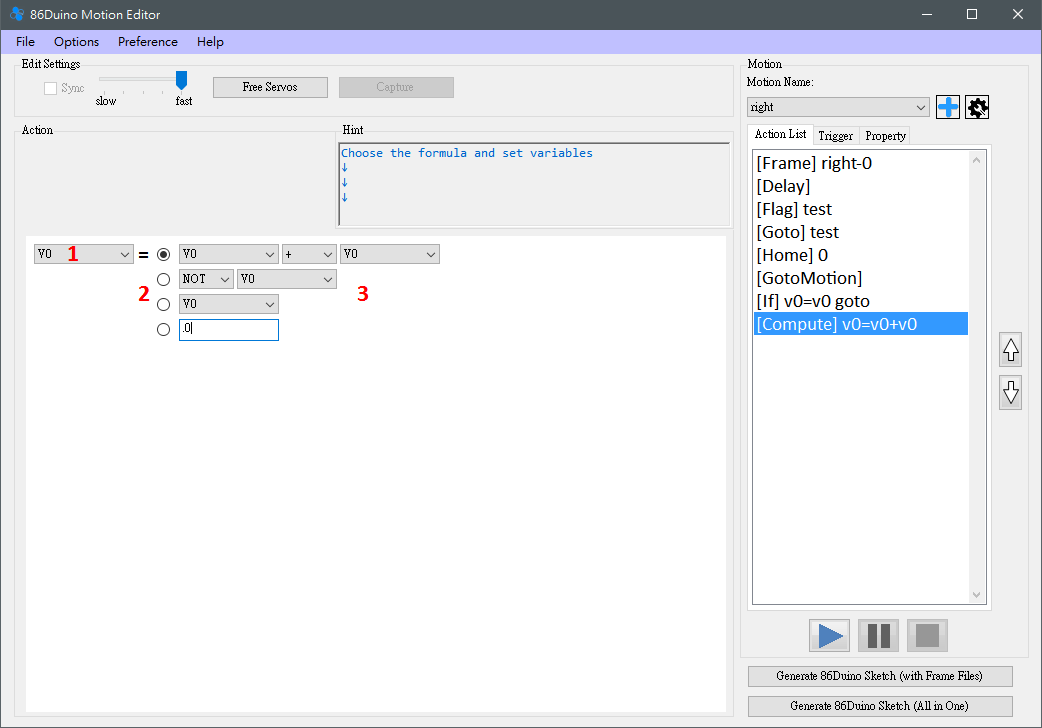
Compute
Compute can be used to do simple calculations and store the values in the specified variables (V0~V49).
- Set the variable of the left sub-formula, you can choose “V0~V49″.
- Select the formula to use. The first formula can perform operations on two variables, including addition, subtraction, multiplication, division, power, remainder, AND operation and OR operation. The second formula provides operations on a certain variable, including NOT, square root, exp, logarithm, absolute value, minus sign, sin, cos. The third formula is a simple assignment. The fourth formula can specify a constant.
- After setting the selected formula, it is completed.
Release
When Release is executed, all servos will stop outputting power. This Action does not need to be set. It will act immediately after being executed. It can be used when the robot is about to encounter danger (such as falling) to prevent the motor from being damaged by excessive force.
Step 5:
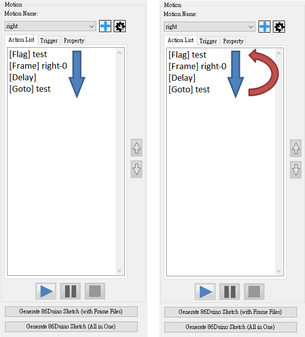
After editing the desired action, you can use the play, pause, and stop buttons to test. The general execution order is as shown in the lower left figure. If you are executing Goto, it is as shown in the lower right figure.
Then, users can choose to continue editing different projects (return to step 2) or different actions (return to step 3). Or select Save Project to generate a .rbm file. The next time you use File->Load Project, you can continue to use the last saved project.
Adding pictures:
The purpose of this function is to allow users to easily match motors, without having to remember which position of the motor corresponds to each time they read the project. You can add robot pictures when adding a new project (File-> New Project) or modifying the project configuration (Options->Robot Configuration). Use the Load RobotPicture button to read PNG, JPG, GIF files as robot pictures. Once read, they cannot be removed. After setting, the Frame type action in the Action List can allow the motor to move freely to achieve the effect of matching the motor with the robot part.
If you save the image after reading it, the saved .rbm file will remember the path of the image in the computer. Therefore, if the image location is changed or removed, it may not be found when reading the project next time. Please pay attention!
Source code
86ME is an open source action editor. The source code is published on GitHub. Interested friends are welcome to download or share. This project is built on Windows 7/10 + Visual Studio 2013 Community Edition.