Link 86Duino to 86Scratch – ESP8266 AP Mode
Wifi module ESP8266 – AP mode
86Duino uses the AP mode of the ESP8266 module for wireless Wifi connection. AP mode changes the ESP8266 module into a wireless base station, which can autonomously send out Wifi signals to provide computer Wifi connection. In this way, as long as the computer has Wifi function (built-in or using a USB wireless network card), 86Scratch can connect to 86Duino via Wifi, without having to consider whether there is free Wifi available on site.
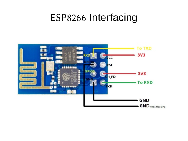
The following figure is the appearance of an ESP8266 EP-01, and you can also see its pin functions:
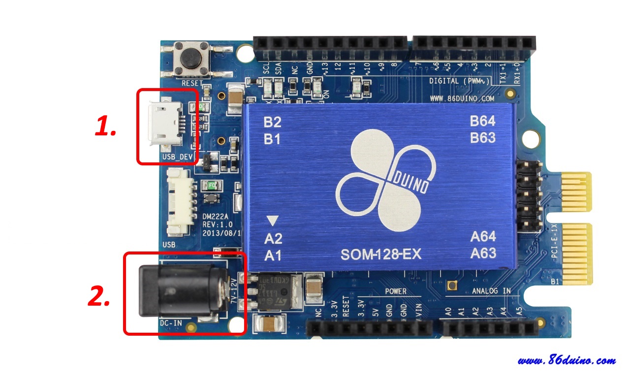
We can connect ESP8266 and 86Duino through Dupont wires and pin headers. Here we take 86Duino ZERO as an example. First, make sure that the USB power supply and external power input interface of 86Duino ZERO are not connected:
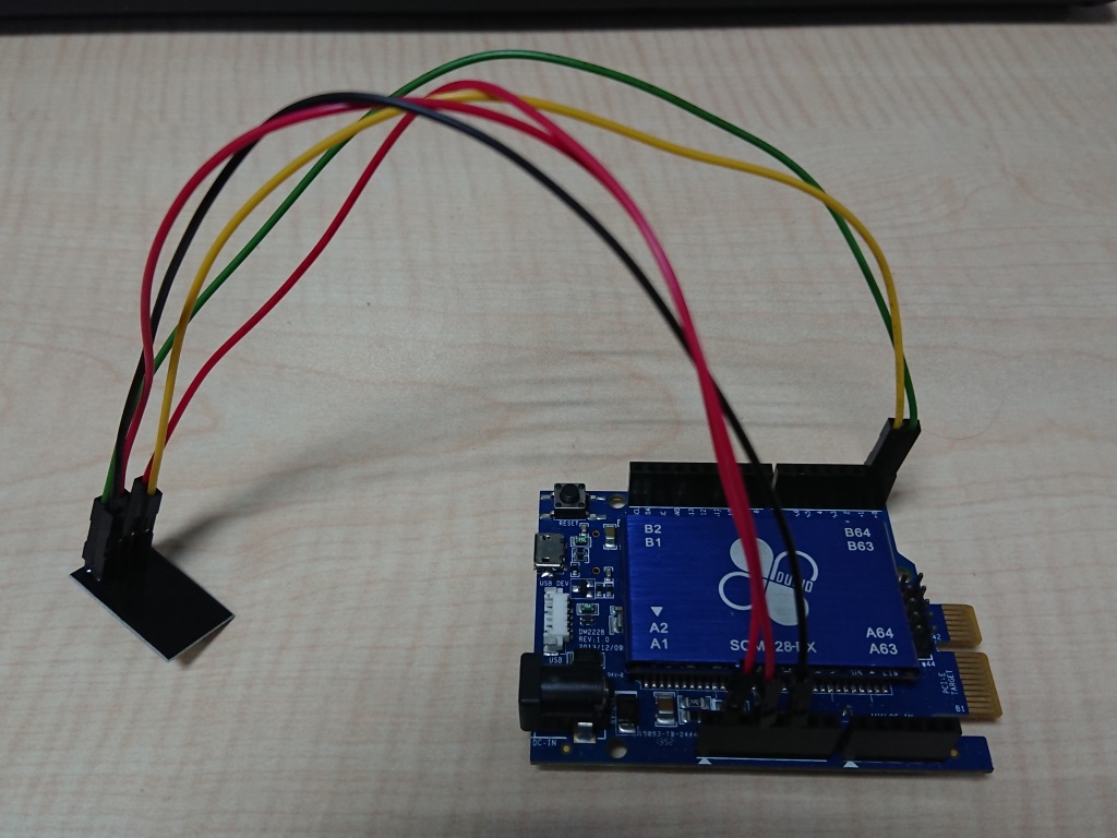
Prepare 5 2.54mm Dupont wire and 5 2.54mm pin headers, and connect the following 10 pins:
- 86Duino ONE's 3.3V connects to ESP8266's VCC (red line in the figure below)
- 86Duino ONE's GND connects to ESP8266's GND (black line in the figure below)
- 86Duino ONE's RX1 connects to ESP8266's TXD (green line in the figure below)
- 86Duino ONE's TX1 connects to ESP8266's RXD (yellow line in the figure below)
- 86Duino ONE's 3.3V connects to ESP8266's CH_PD (red line in the figure below)
CH_PD is Chip Power Down means that the CH_PD pin of ESP8266 must be connected to a high potential (3.3V) for ESP8266 to operate normally. If it is connected to ground (GND), it will enter power saving mode (Power Down) and turn off Wifi, so here we just connect CH_PD directly to 3.3V.
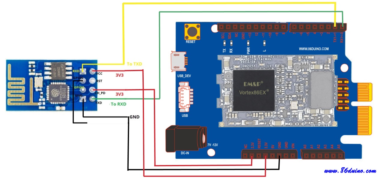
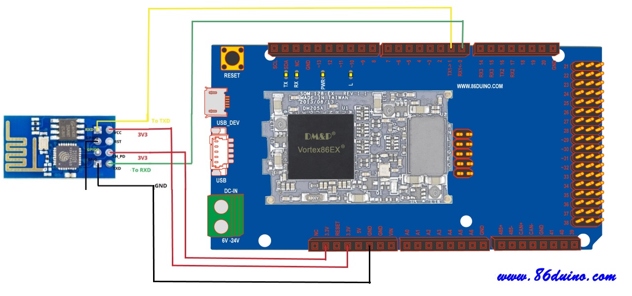
86Duino ZERO wiring diagram:
If you replace 86Duino ZERO with 86Duino ONE or 86Duino EduCake, you can still connect HC-06 by following the above steps. The only difference is the position of the pins.
86Duino ONE wiring diagram:
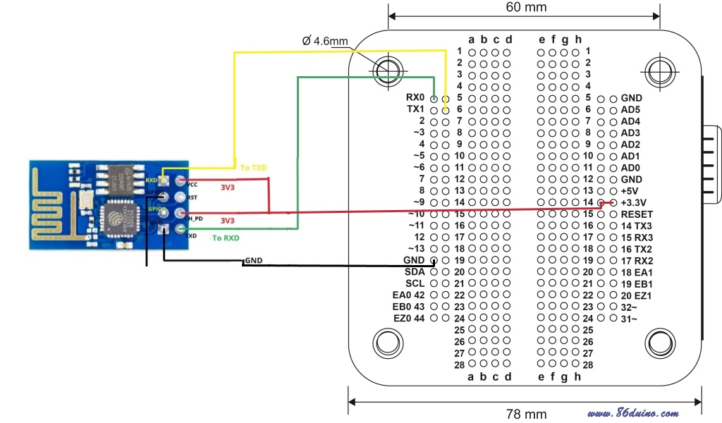
86Duino EduCake wiring diagram:
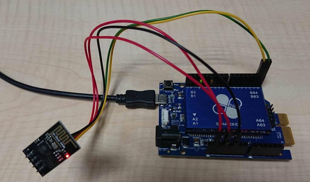
After wiring, please connect the USB power supply to confirm whether the ESP8266 module is powered normally (the red power light will light up as shown in the figure below).
ESP8266 AP connection settings
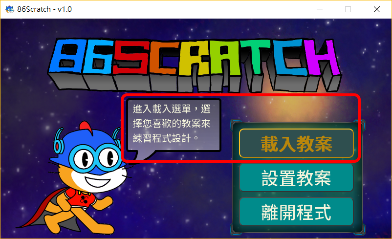
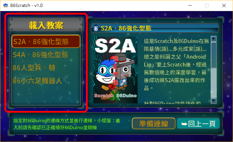
After opening 86Scratch, please click "Load lesson plan" to enter the lesson plan selection screen:
In the lesson plan selection screen, you can see that there are 4 lesson plans to choose from. When you move the mouse to different lesson plans, the instructions about the lesson plan will appear. Please select here "S2A.86 Enhanced Mode" lesson plan, and click "Ready to connect" to proceed to the next step:
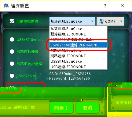
After the connection setting window appears, if the last time you connected 86Duino was not using ESP8266 AP connection or it is the first time to connect 86Duino, please check "Automatically burn firmware" and select 86Duino ZERO's ESP8266 AP connection firmware. Since the computer has not yet connected to the ESP8266 wireless base station, only the firmware is burned here. Please select "Do not open Scratch" for the connection method:
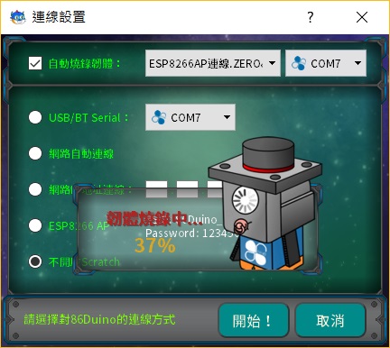
After the settings are completed, click "Start!" to start burning the firmware:
After the firmware is burned, it will return to the screen for loading the lesson plan:
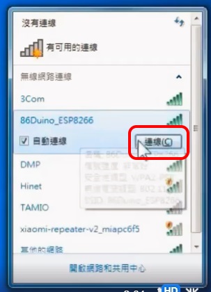
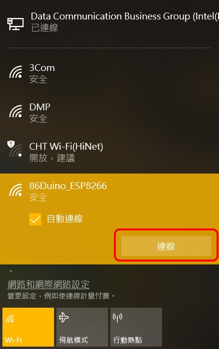
At this time, ESP8266 has been set to WiFi AP mode by the firmware just burned. Click In the Internet access in the Windows taskbar, we will see a wireless Wifi named "86Duino_ESP8266" available for connection:
Windows 7:
Windows 8/10:
Enter the default network security key "1234567890" in the firmware, and then click "OK" (Windows 7) or "Next" (Windows 8/10): Windows 7: 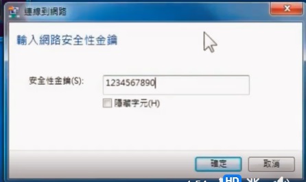 Windows 8/10:
 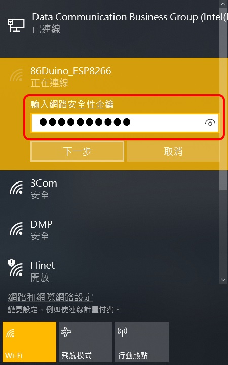 At this point, the Windows computer will start connecting to the AP of the ESP8266.
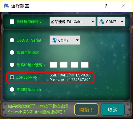
After successfully connecting to 86Duino_ESP8266 in Windows, please select the "S2A.86 Enhanced Mode" lesson plan and click "Ready to Connect" to enter the connection settings window:
After entering the connection settings window, please select "ESP8266 AP" connection (no need to burn firmware):
86Scratch starts with Wifi Connect to 86Duino ZERO: 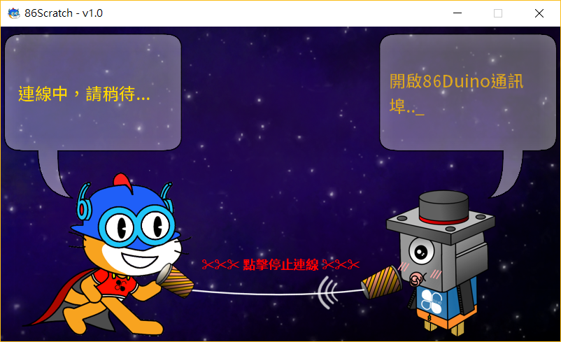
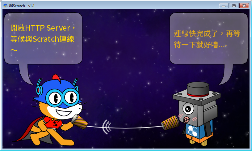
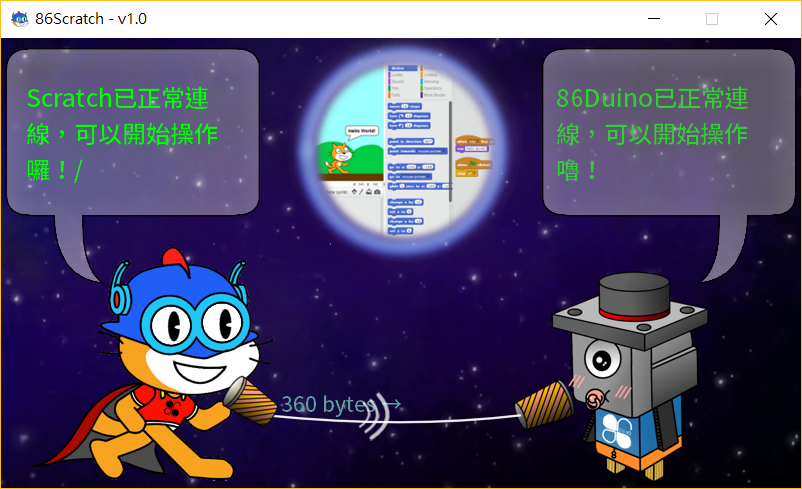
During the process, 86Scratch will try to connect to 86Duino. You can see that the 86Scratch cat on the left and the 86 fungus on the right are talking to each other through a microphone. When you see the following dialogue screen, it means that the connection is almost successful:
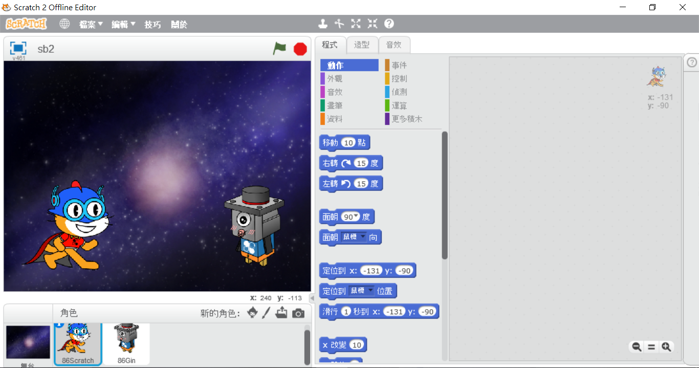
At this time, 86Scratch will automatically open Scratch 2.0 on the computer for us (and will also load the S2A enhanced 86Duino building blocks at the same time) :
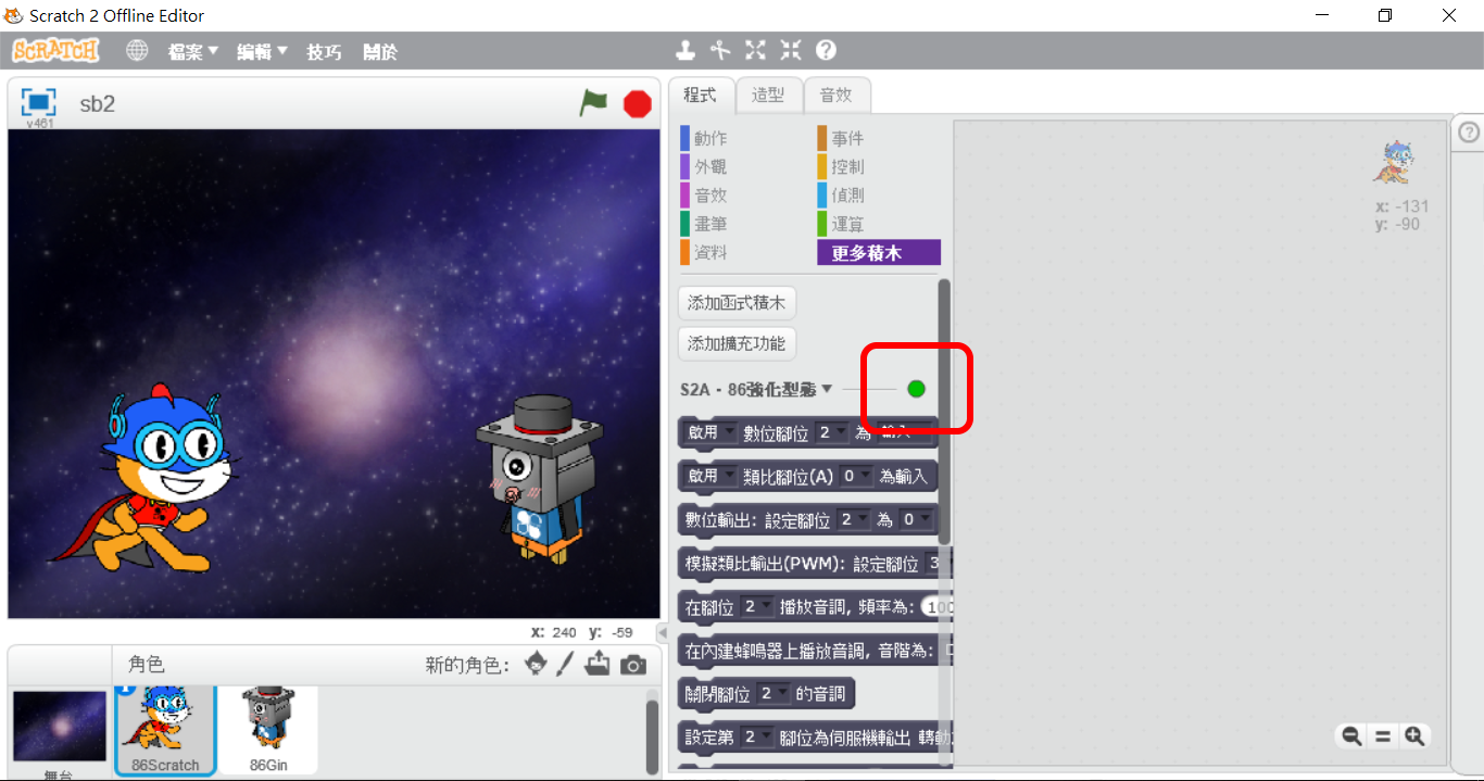
Click "More Blocks" to find the "S2A‧86 Enhanced Type" block. There is a light next to the block. It is red in normal state. When 86Scratch successfully connects the block to 86Duino, the light will turn from red to green:
When the light turns green, switch back to the 86Scratch window and you will see the following screen:
Now the connection is successful, you can start writing programs!!
Smart Pot Watering Treasure
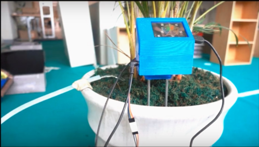
ZaiBo is an open source project that uses wireless Wifi to remotely monitor plant watering conditions.There is an open source source code for reference on GitHub. In the project, Lubuntu (linux OS) is installed in the Micro SD card as the boot disk of 86Duino ZERO. The ZaiBo APP is used to perform real-time monitoring of the potted plant environment and automatic watering in Lubuntu:
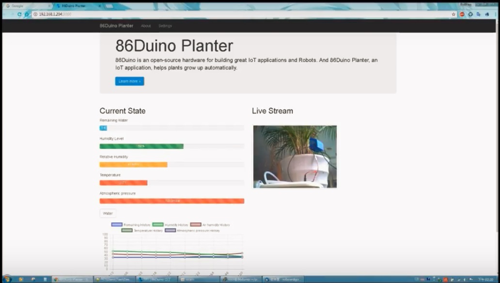
The ZaiBo APP sets up a website in Lubuntu, allowing users to remotely monitor the potted plant environment through Wifi connection.
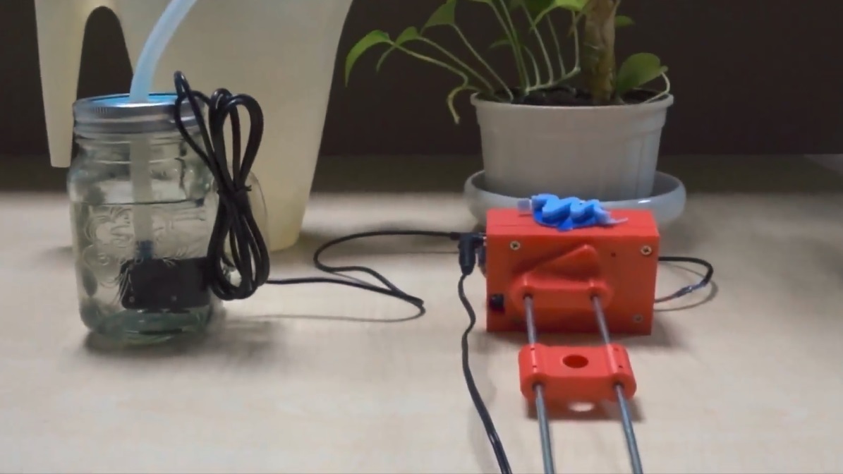
Can a simple IOT automatic watering system be realized with only 86Scratch? Of course it can!! Taking the function of reading humidity to determine whether to control the motor to pump water as an example, we only need a simple version of the Zaibao hardware component:
The 86Duino in Zaibao also uses 86Duino ZERO, so you only need to follow the previous ESP8266 AP connection steps to connect 86Scratch to the 86Duino ZERO in Zaibao :
After the connection is successful, let's start programming the 86Duino IOT automatic watering system!!
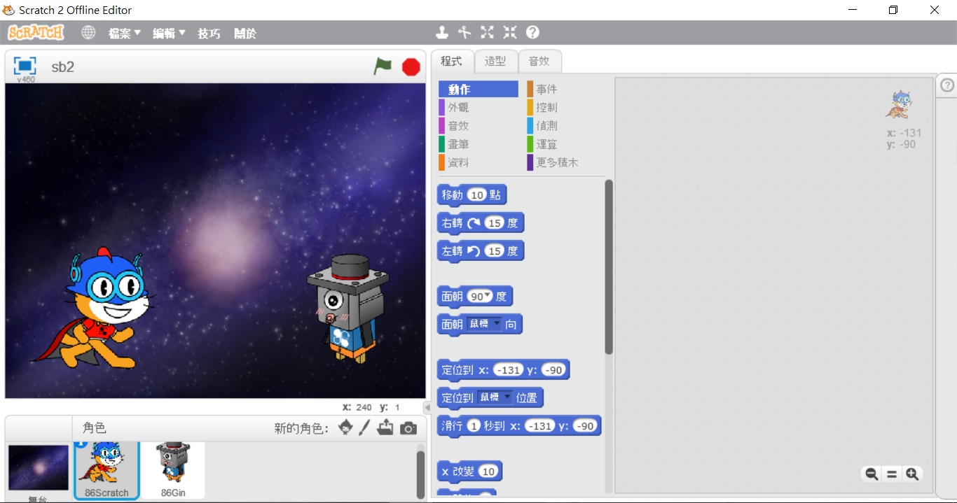
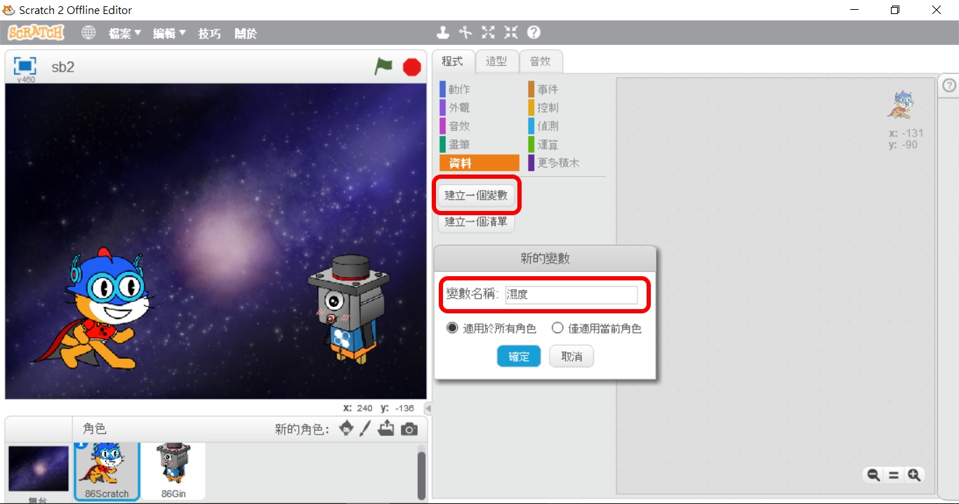
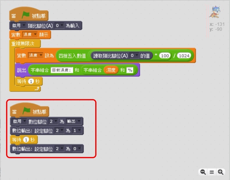
1. Create a variable "humidity" to store the humidity read:
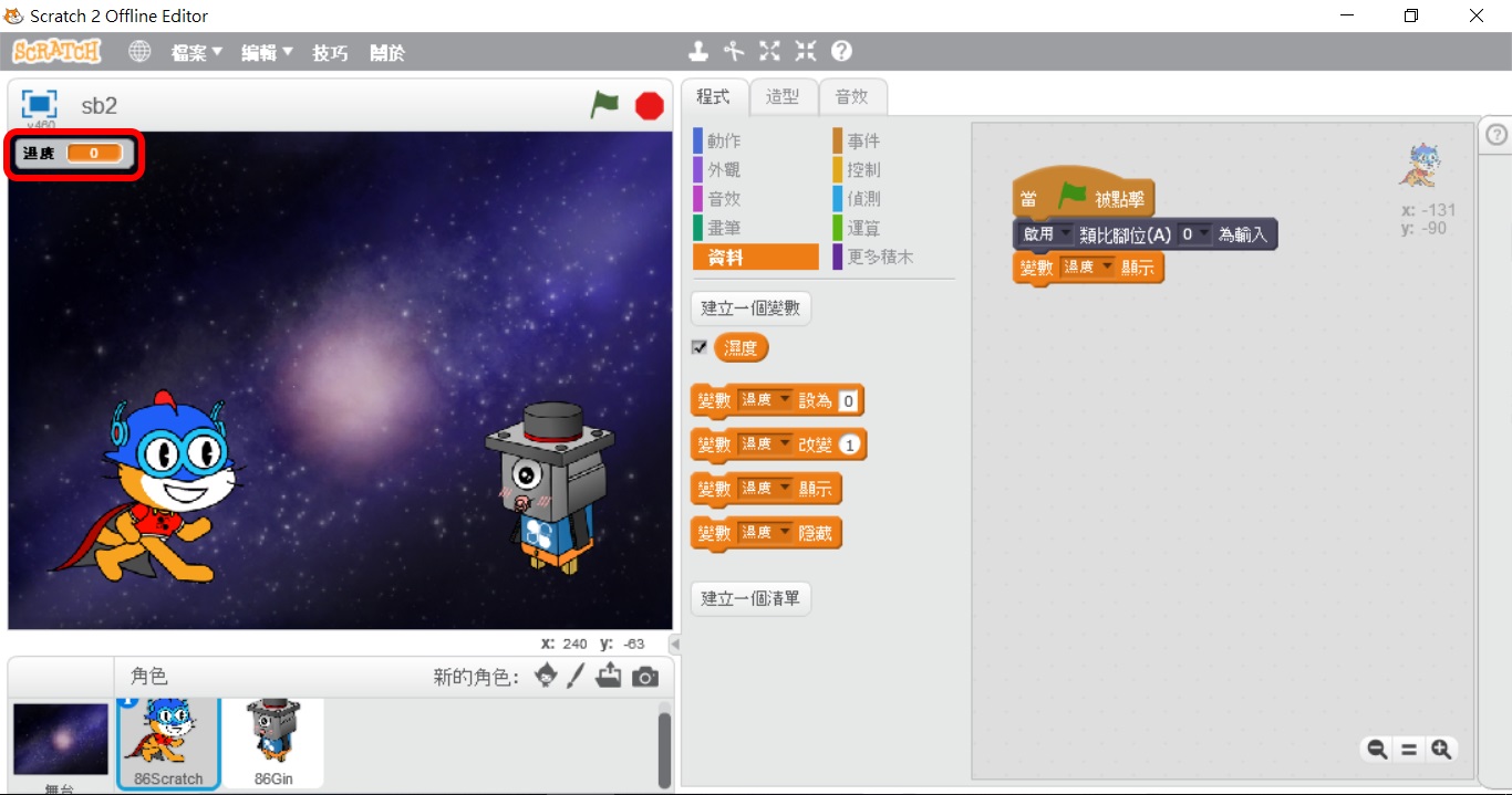
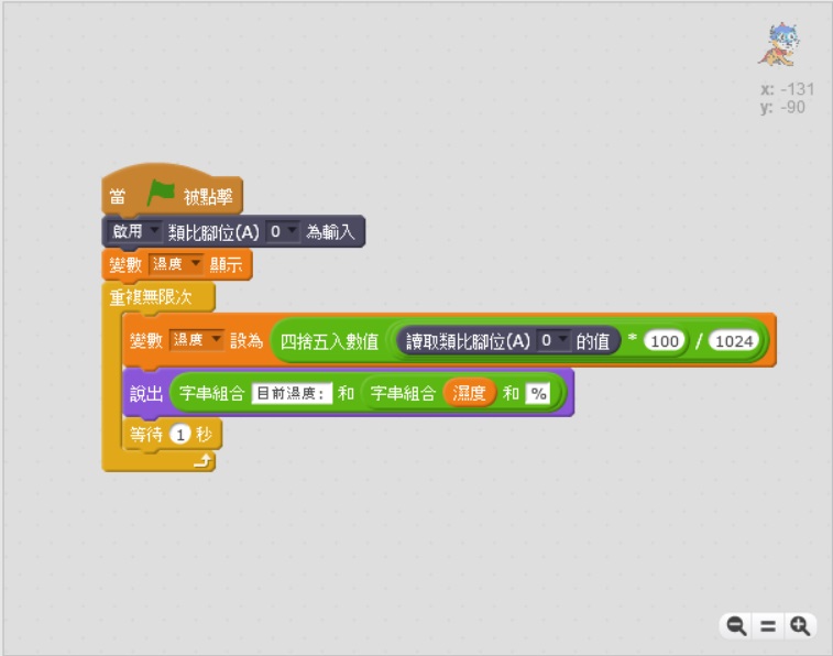
2. The humidity sensed by the metal detector can be obtained by reading analog pin 0, so analog pin 0 must be enabled as input and the variable "humidity" is displayed on the Scratch 2.0 stage:
3. Repeatedly read analog pin 0 to obtain humidity information. The result of reading analog pin 0 multiplied by 100 and divided by 1024 is the percentage of humidity:
4. Try to start the pumping motor for 1 second:
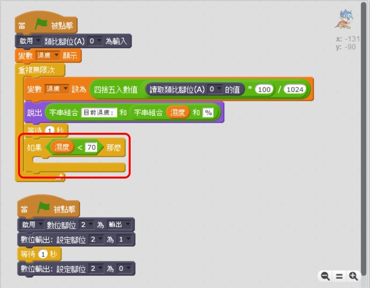
5. Add humidity judgment mechanism:
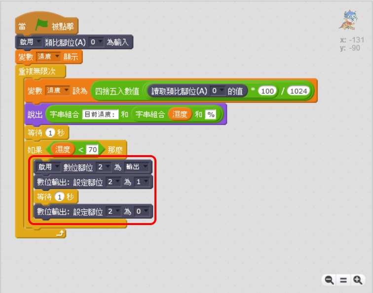
6. Put the action of starting the pumping motor for 1 second into the humidity judgment mechanism. If the humidity is lower than the target (70), watering will be executed:
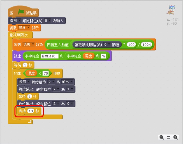
7. Originally, the 86Duino IOT automatic watering system should have been completed here, but the soil humidity cannot change immediately after the watering action is executed, resulting in the watering action being executed 2 times or even 3~4 times in a row (affected by soil differences). To solve this problem, try waiting for 10 seconds after watering:
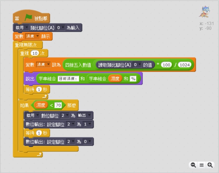
8. Waiting for 10 seconds after watering solves the problem of continuous watering, but Scratch Cat will have 10 seconds after watering. 1 second stop time, doesn't it feel dynamic enough? In order to make Scratch Cat dynamic without over-watering continuously, we modified the system to have 2 action cycles, monitoring soil moisture once every 1 second, and judging whether to water once every 10 seconds:
After completing the above building block program, Scratch Cat can start to be a potted plant manager.
The text of the 86Duino reference is licensed under a Creative Commons Attribution-ShareAlike 3.0 License. Code samples in the reference are released into the public domain.