86Duino Motion Editor v1.9
The 86Duino Motion Editor (86ME) supports the 86Duino development board for editing robot motions, making editing robot motions much faster. It also automatically generates 86Duino programs for robot operation and editing. 86ME Concept Video:
Installation Instructions
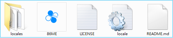
Currently, the 86ME supports Windows XP/Vista/7/8/10. Microsoft .NET Framework 4.0 must be installed. Download 86ME and unzip it. You'll find the folder 86ME. The files inside, as shown below, include the 86ME executable, required libraries, and instructions. To start using 86ME, simply execute 86ME.exe in a supported environment.
Preparation
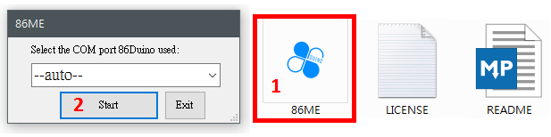
Therefore, offline mode only supports file editing and 86Duino program generation, not real-time motor control. To directly control motor motion, connect the 86Duino's USB device to your computer's USB port and select the COM port to which the 86Duino is connected (either automatically or by selecting a known COM port). To confirm which port the 86Duino is connected to, try locating the 86Duino and its connected COM port in Device Manager. As shown in the example below, the 86Duino is connected to COM4 on the computer. If you select Automatic Mode without an 86Duino connected, the program will switch back to Offline Mode during execution. 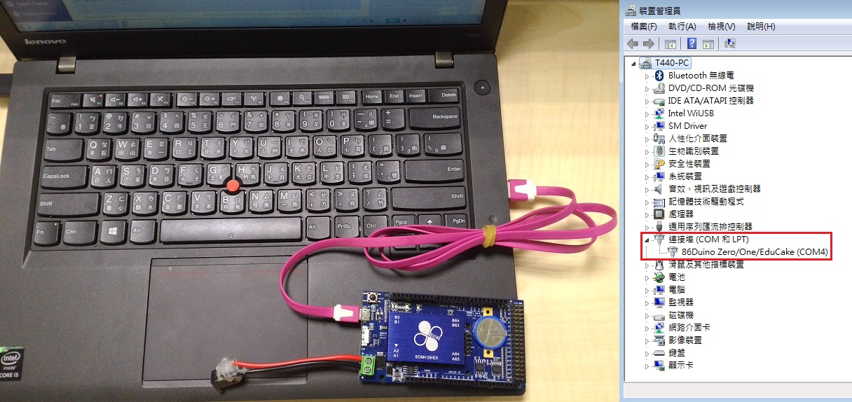 Generally speaking, Offline Mode is more suitable for users who are already very familiar with the robot's movements, allowing them to easily edit existing files and make adjustments. Automatic Mode allows users to easily start using the 86ME. However, if your computer is connected to multiple 86Duinos or multiple different COM ports, Selected Mode is recommended to avoid confusion. Once you've configured the COM port, press the Start button to enter the 86ME main window or the Exit button to exit.
Functional Description
Here, we'll first explain the programming interface by dividing it into several sections. 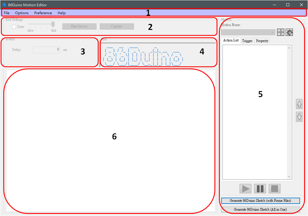
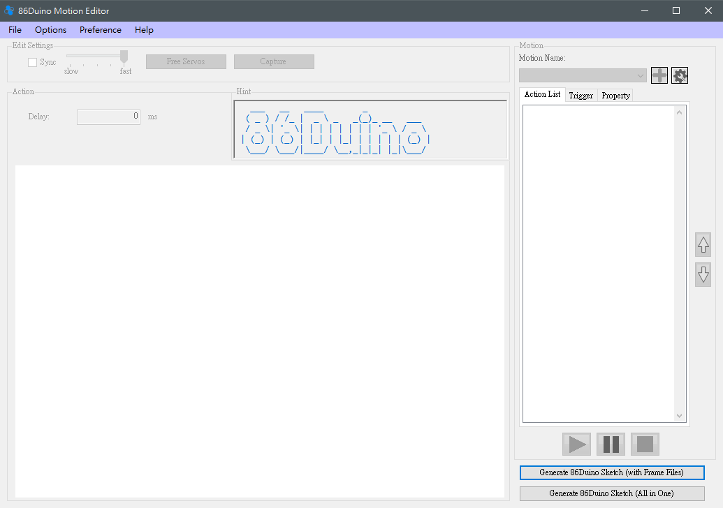
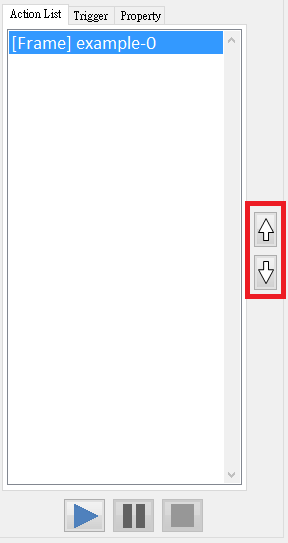
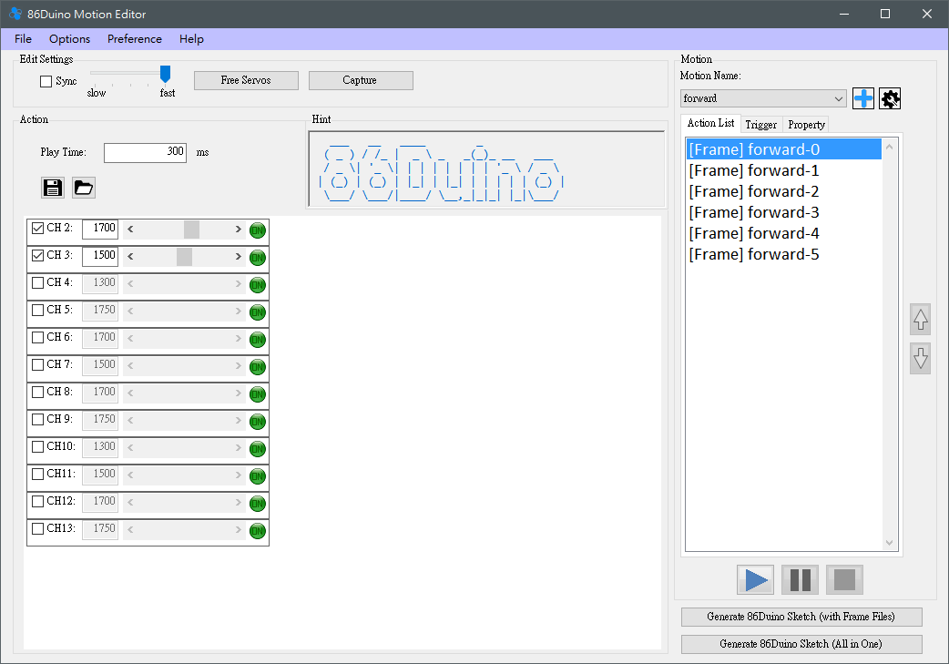
(1) The Sync function allows the user to decide whether to synchronize the currently selected Frame to the robot immediately.
(2) The slot machine here can determine the speed of the motor during sync. There are five levels, with the right side being the fastest and the left side being the slowest.
(3) Release the motor, so that the motor no longer outputs power.
(4) Capture, used to read the current motor angle. Currently supported motors are from the Kondo, Hitec, and Futaba series. Please be careful when using it, because the Capture function will release all motors first. If the robot is not properly supported, it may fall.
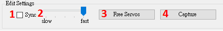
(1) Set the time to move to this action in milliseconds.
(2) When the selected Action is Frame, two buttons will appear in the Action area to save/read 86Duino Frame File. The Save function can save the currently selected Frame to the current frame. The servo angles are stored in a text file, and the read function can load the saved frame file values into the current frame.

- Establishing a Bridge Between 86Duino and 86ME: The 86ME will transmit commands to the 86Duino via the Firmata library. Therefore, when using the 86ME Before you begin, you'll need to download the 86Duino Coding 210 example (File -> Examples -> Servo86 -> MotionEditor) to the 86Duino. Once the communication bridge is established, you can officially begin operating the 86ME.
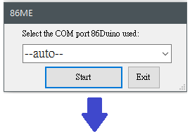
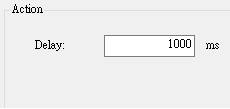
- Connection Methods and Instructions: Currently, the 86ME supports connecting to the 86Duino via a computer's COM port and sending motion signals. Initially, the 86ME will ask the user to select the interface between the 86Duino and the computer. There are three modes for initializing the connection: Auto, Offline, and Selected. Before running 86ME.exe, you must understand these modes. The –auto– option in the figure opens the last added COM port. COM4 indicates that the 86ME has detected the current COM port on the computer. The –offline– option indicates offline mode, which will prevent communication with the 86Duino.
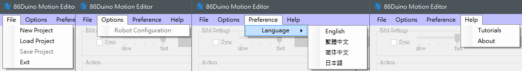
- This section has three drop-down menus: File, Options, and Help. The expanded options are as follows:
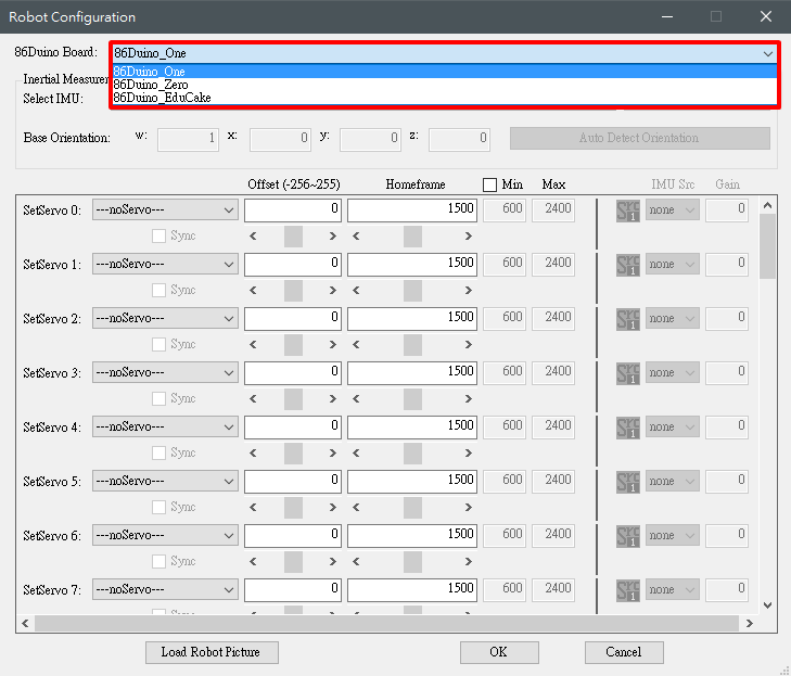
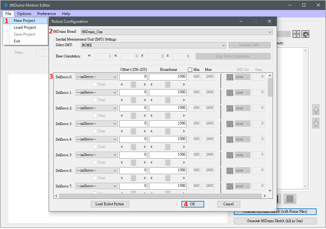
- (1) The functions of the File menu include adding a new project, loading a project, saving a project, and exiting a program. Sharp-eyed readers may notice that many buttons are gray and unclickable at first. To edit or test an action, you must first create a project using File->New Project or load a previously saved project using File->Open Project. File->Save Project can save the currently edited project, and File->Exit can exit a program. So how do you add a new project? Clicking File->New Project will bring up the Robot Configuration window, where you can configure four robot-related settings. (1) 86Duino Board: This is used to select the 86Duino model used by the robot. Currently, there are 86Duino One/Zero/EduCake for users to choose from. Selecting different 86Duino models will open a different number of SetServo pins for the user to configure. For example, the 86Duino One has 45 pins that can control motors, so SetServo 0-44 will appear, while the 86Duino Zero will only have SetServo 0-13 and 42-44.
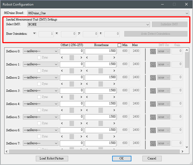
- (2) IMU Settings: Set the Inertial Measurement Unit (IMU) used by the robot. Currently supported IMU models include the built-in IMU on the 86Duino One and the RM-G146. After selecting an IMU model and entering connection mode, you can use the "Initialize IMU" button to initialize the IMU connected to the 86Duino and use the "Auto Detect Orientation" button to detect the current IMU base orientation. Only after completing these settings can the IMU compensation function be used correctly to facilitate robot balance.
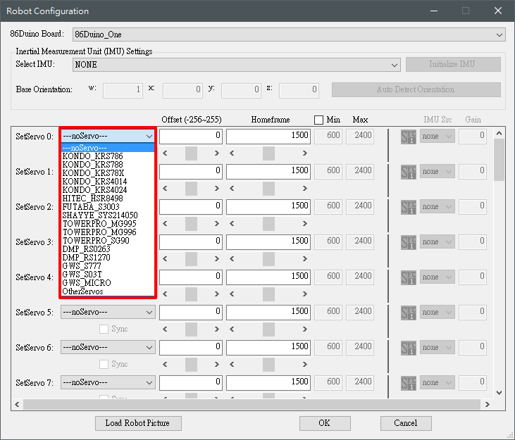
- (3) SetServo: Used to set the motor connected to the 86Duino. The motor model, offset, home frame, maximum value (Max), and minimum value (Min) supported by the motor are provided for user settings. The currently supported motor models are as follows:
- After selecting a motor, you can adjust the offset and starting position using the scroll bar control options shown below. Checking the Sync control synchronizes the offset and starting position angles to the motor, allowing for real-time adjustments. The motor's acceptable range automatically changes after selecting the motor. To manually adjust it, you must first check the min/max control in the upper right corner. If you have an IMU configured, you can enable IMU compensation by setting the IMU Src field, select the compensation source, and set the compensation factor using the Gain field. To add a second compensation source, click the Src 1 icon to switch to Src 2.
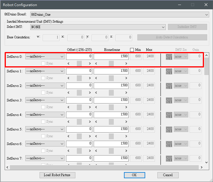
- (4) Load Robot Picture: To facilitate the mapping of motor positions to various parts of the robot, users can select a picture as a representative image of the robot. Detailed usage will be explained in the following section.
- Options menu contains the Robot Configuration option, which is used to edit the current robot-related settings. The content is similar to File->New Project.
- Preference menu allows users to select the language of the operation interface. Currently, it supports English, Traditional Chinese, Simplified Chinese, and Japanese.
- Help menu contains Tutorials and About Clicking Tutorials will redirect you to the 86ME documentation on the 86Duino website, while About will display information about the 86ME, such as the author and the official 86Duino fan page.
- (1) The functions of the File menu include adding a new project, loading a project, saving a project, and exiting a program. Sharp-eyed readers may notice that many buttons are gray and unclickable at first. To edit or test an action, you must first create a project using File->New Project or load a previously saved project using File->Open Project. File->Save Project can save the currently edited project, and File->Exit can exit a program. So how do you add a new project? Clicking File->New Project will bring up the Robot Configuration window, where you can configure four robot-related settings. (1) 86Duino Board: This is used to select the 86Duino model used by the robot. Currently, there are 86Duino One/Zero/EduCake for users to choose from. Selecting different 86Duino models will open a different number of SetServo pins for the user to configure. For example, the 86Duino One has 45 pins that can control motors, so SetServo 0-44 will appear, while the 86Duino Zero will only have SetServo 0-13 and 42-44.
- The Edit Settings section has the following functions.
- Action block, can be used
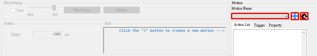
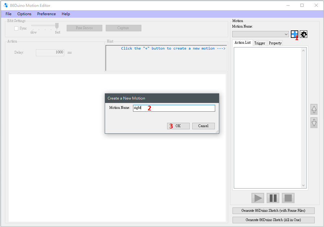
- The Hint block provides the user with some operational tips, such as how to add an action list, precautions when executing an action, etc. If you have already registered the 86ME It's very familiar, allowing you to program as you see fit. These tips are primarily for beginners, providing the next steps. The Motion section is used to edit and test the robot's motions. Each motion is separated by a "Motion Name." For example, you can add motions like walking, punching, and crouching. Pressing the "+" button will pop up a window allowing you to select a "Motion Name," as shown below:
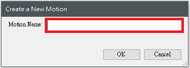
Press "OK" to add the motion. To add another motion, press "+" and repeat the same process. To edit an existing motion, use the scroll bar in the "Motion Name" field. The gear-shaped button on the far right provides several motion management functions, including copying, renaming, deleting, importing, and exporting.
 Action List:
After creating a Motion, you can begin editing the Action List. For example, if an action requires four frames to render, right-click in the Action List to add a new action.
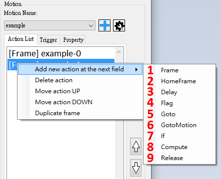
The main operations of the Action List are
(1) Add an Action, there are nine types of Actions in total
(2) Delete the selected Action
(3) Move the selected Action up one grid
(4) Move the selected Action down one grid
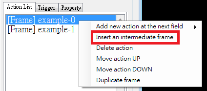
(5) You can copy a Frame or HomeFrame In the next cell, you can also use the two buttons below to move it up and down.
The Action List also has a convenient feature. When a frame is immediately followed by another frame, a function is enabled to insert a new frame. The angle of each motor is the sum of the corresponding motors in the two frames before and after, divided by two. This feature is convenient for editing two frames with large movement distances. Adjusting the action parameters is explained in Section 6 and the usage examples.
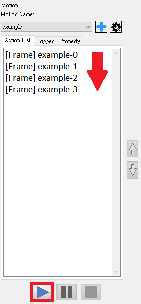
After editing the action list, if it is connected to the 86Duino, press the play button to test the action list. From the first to the last action in the project, users can use this function to test the motion.
Trigger:
The two buttons at the bottom export the current project to a program that can be burned into the project. The 86Duino ino program file. "Generate 86Duino Sketch (with Frame Files)" generates an ino file and several motion configuration files, while "Generate 86Duino Sketch (All in One)" writes all the settings into a single ino program. The generated file is based on all currently edited motions, plus each motion's trigger and property. Trigger settings are set by selecting a motion and going to the Trigger tab. Currently, five trigger types are supported: auto, keyboard, Bluetooth, PS2 controller, and accelerometer.
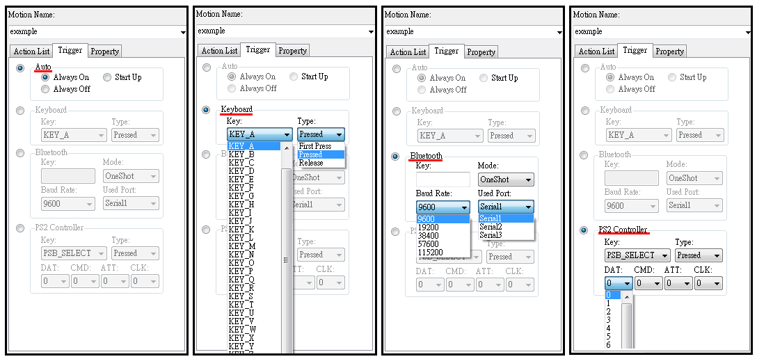 (1) Auto is divided into Always On, Always Off, and Start Up. Always On means that this action will always be displayed, Always Off means that this action will never be displayed, and Start Up will be displayed once when 86Duino starts.
(2) Keyboard can set the Key and Type. Key currently provides A~Z and up, down, left, right, blank, and ESC. Type provides First Press, Pressed, and Release. Motion will be triggered when the Key and the corresponding state are met. For example, the robot's walking is set to Key A, Pressed, and the robot's return to standing position is set to Key A, Release. When we press the A key, the robot will keep walking, and releasing the A key will return to standing position. If it is more perfect, you can also add Key A and First Press as the starting step for half-step.
(3) Bluetooth can select a single-character Key input, as well as the Mode and Baud Rate and Serial Port of the Bluetooth module. For example, we assemble the Bluetooth module in Serial1 of 86Duino, set the Key of the forward motion to B, generate the program and burn it, then you can use the mobile phone APP software (currently only supports APPs that send single characters) to send signals to control the robot to move forward. The Mode options are divided into OneShot and Continuous. OneShot mode will trigger the action only once, which can be used for the robot to punch, kick, etc., while Continuous will trigger the action continuously, which can be used for forward, backward, etc.
(4) PS2 Controller can select the button on the PS2 joystick as the Key , and the Type that triggers this button can be set just like a keyboard. In addition, if you want to use a PS2 joystick to control the robot, you must also set the four pins connecting the PS2 and 86Duino, namely DAT (data), CMD (command), ATT (attention), and CLK (clock). These four pins correspond to the 86Duino pins.
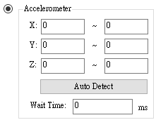
(5) The Accelerometer function allows you to select the accelerometer's X, Y, and Z axis readings as trigger conditions. Simply set the ranges for each axis and the duration for the readings to remain within these ranges. The "Auto Detect" button automatically detects the current accelerometer readings and selects the range to fill in the blanks after the IMU is correctly initialized in the Robot Configuration window.
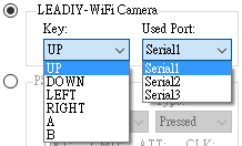
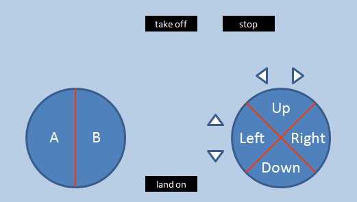
(6) WiFi Camera (WiFi602) is a video streaming module with 5V, GND, TX and RX pins. After powering on, it will establish a WiFi AP. Let the phone connect to this WiFi and open the APP to obtain the stream. In addition, it can also be used via the Serial Port To transmit the app's button status, you need to select a serial port. Currently supported keys include Up, Down, Left, Right, A, and B, and their locations in the app are shown below.
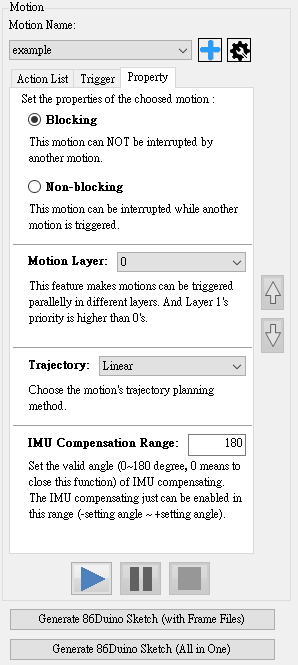
Property settings are currently divided into:
(1) Blocking and Non-Blocking: Blocking motions will not be interrupted by other motions in the generated program, while non-blocking motions will be interrupted by other motions.
(2) Motion Layer: Sets the layer where the motion is located. This function allows motions of different layers to be triggered simultaneously. For example, when a humanoid robot is moving, it can still trigger a punching motion. However, if two layers of motion use the same servo, there will be a priority issue. Here, the motion of layer 1 will take precedence over that of layer 0. Therefore, after an motion is set as Motion Layer 1, the user needs to check the servos to be used in the Frame properties, as shown in the figure below. In this way, when the motions of layer 0 and layer 1 are triggered at the same time, the selected servos CH 2 and CH 3 will take priority to execute the motion edited in layer 1.
(3) Trajectory: Sets the motion trajectory planning method. Currently, three methods are supported: Linear, Constrained Cubic, and Natural Cubic. The two Cubic planning methods can reduce the vibration generated during movement compared to Linear, and the Natural Cubic planning method has the most significant effect. However, the Natural Cubic planning method may have overshooting. The curve of the action may become too large. The Constrained Cubic planning method can avoid this problem, but the effect of reducing vibration is not as amazing as the Natural Cubic. The two Cubic planning methods currently only support actions that are all Frames, that is, they cannot contain actions other than Frames. If there are other actions, they will automatically degenerate back to Linear. Please pay attention when using them.
(4) IMU Compensation Range: Set the effective angle of the IMU compensation function (0~180 degrees, 0 means the compensation function is turned off). The IMU will only generate compensation values within the (-set value ~ +set value) angle. This function can set the effective range of compensation. If some actions do not require compensation, you can also set it to 0 to turn off compensation. There are two types of programs that are finally generated, and their burning methods are slightly different.
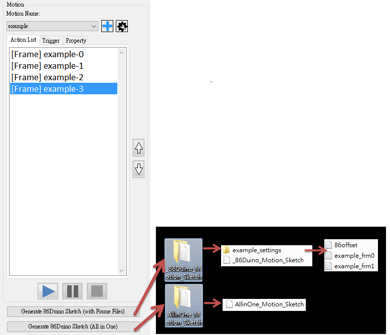 In addition to burning the INO program into the 86Duino, you also need to place the generated configuration file folder into the 86Duino SD card ( Generate 86Duino Sketch (with Frame Files) href="http://www.86duino.com/index.php?p=3203&lang=TW">Create 86Duino SD Card) to run correctly. Generate 86Duino Sketch (All in One) will only generate one INO program; simply burn it into the 86Duino.
Usage Example
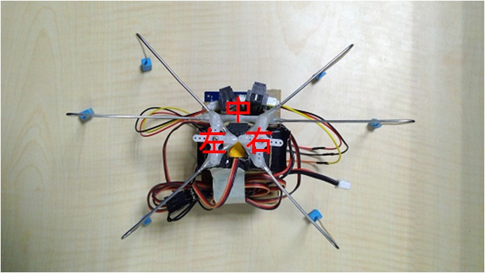
This example aims to help users understand the operation of the 86ME. It uses the 86ME to operate a hexapod robot with three servo motors as an example. These six-pin boards are based on an 86Duino Zero and three DMP_RS0263 chips. The left, center, and right pins correspond to pins 11, 43, and 44 on the 86Duino, respectively.
Step 1:
Step 2:
Step 3:
Step 4:
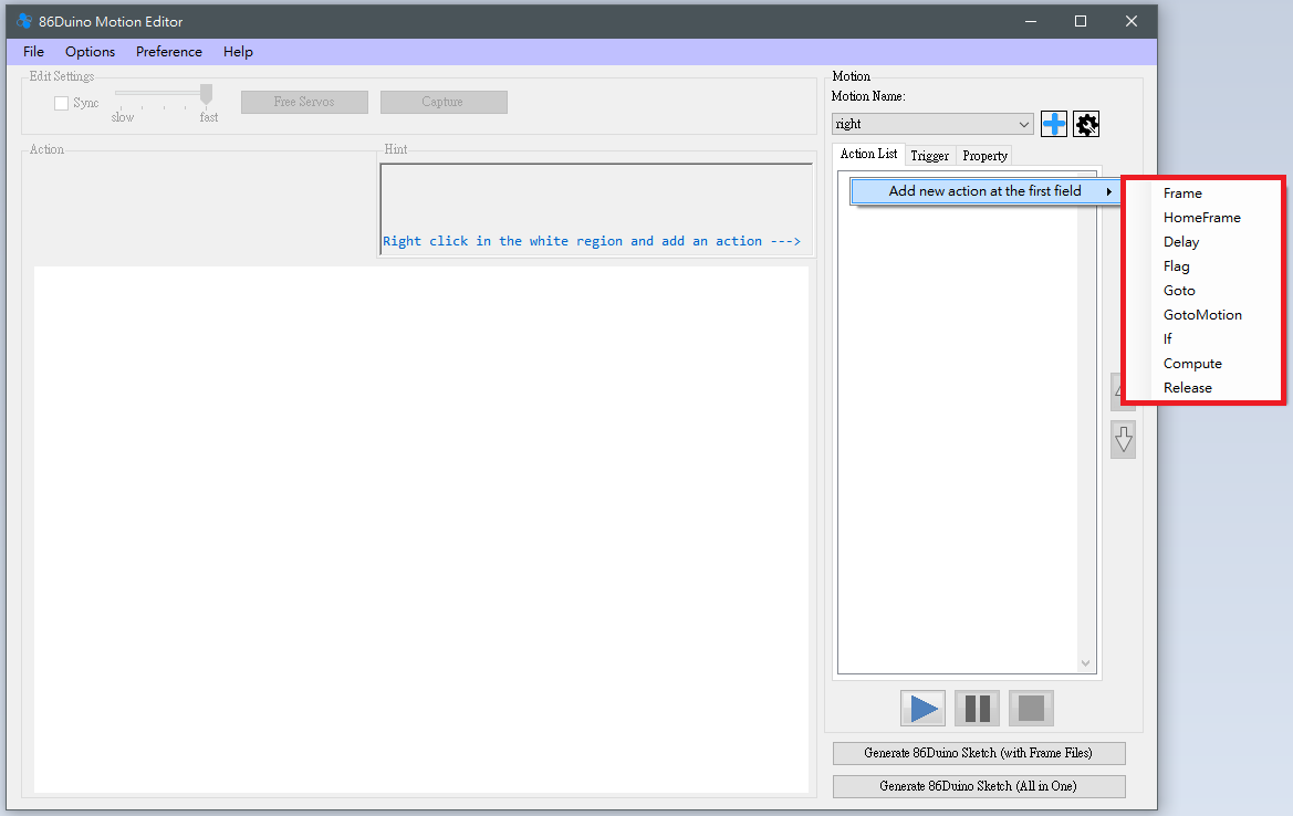 Right-click in the blank area below the Action List -> Add action at the first field. Select an action to add it to the list.
There are nine Actions, their functions are described below.
Frame
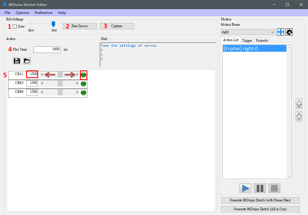
After selecting Frame, you can adjust the three motors you previously configured, and several functions will be enabled for user adjustment.
Delay
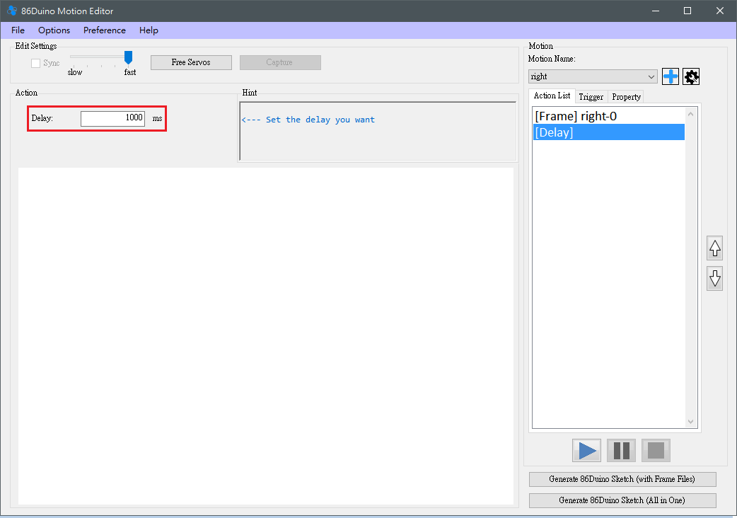 This allows the user to set a delay. This delay is simply a pause and will not cause the robot to move.
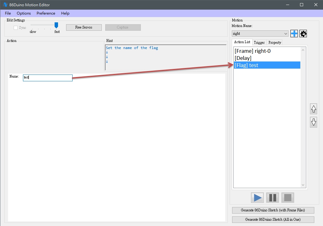
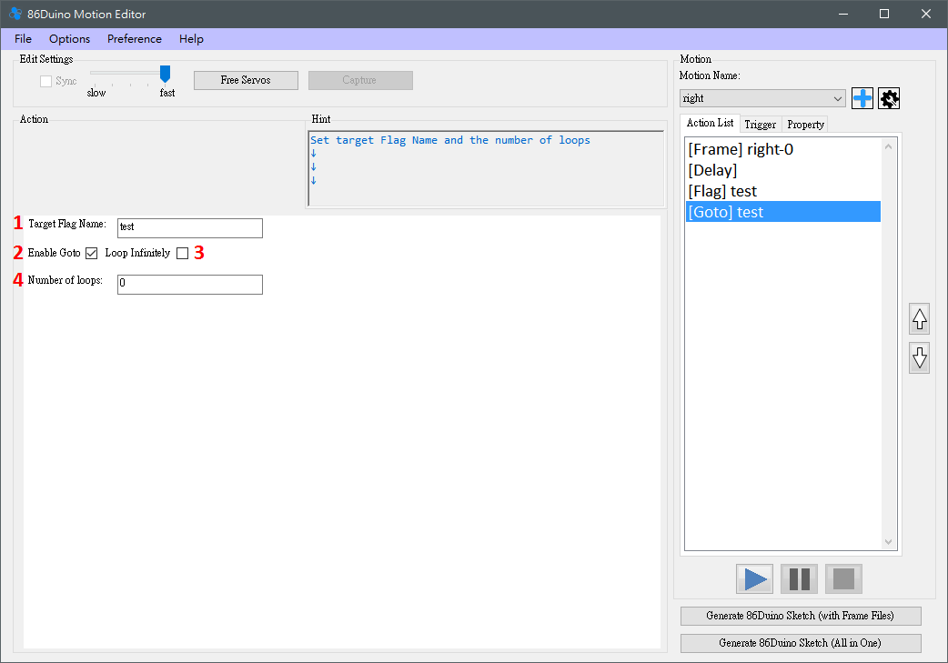
Flag & Goto
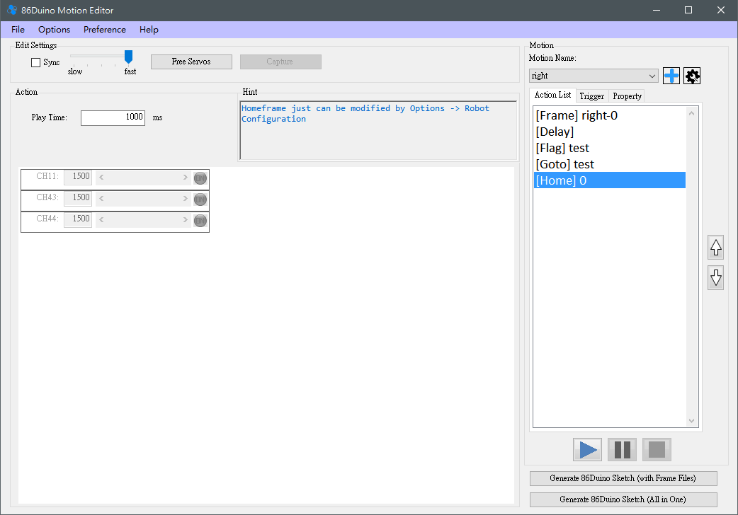
HomeFrame
Selecting HomeFrame adds a frame with an unchangeable initial position. The HomeFrame value can only be changed in Options -> Robot Configuration. This option is for easy homing and allows users to identify where the homing action will be executed.
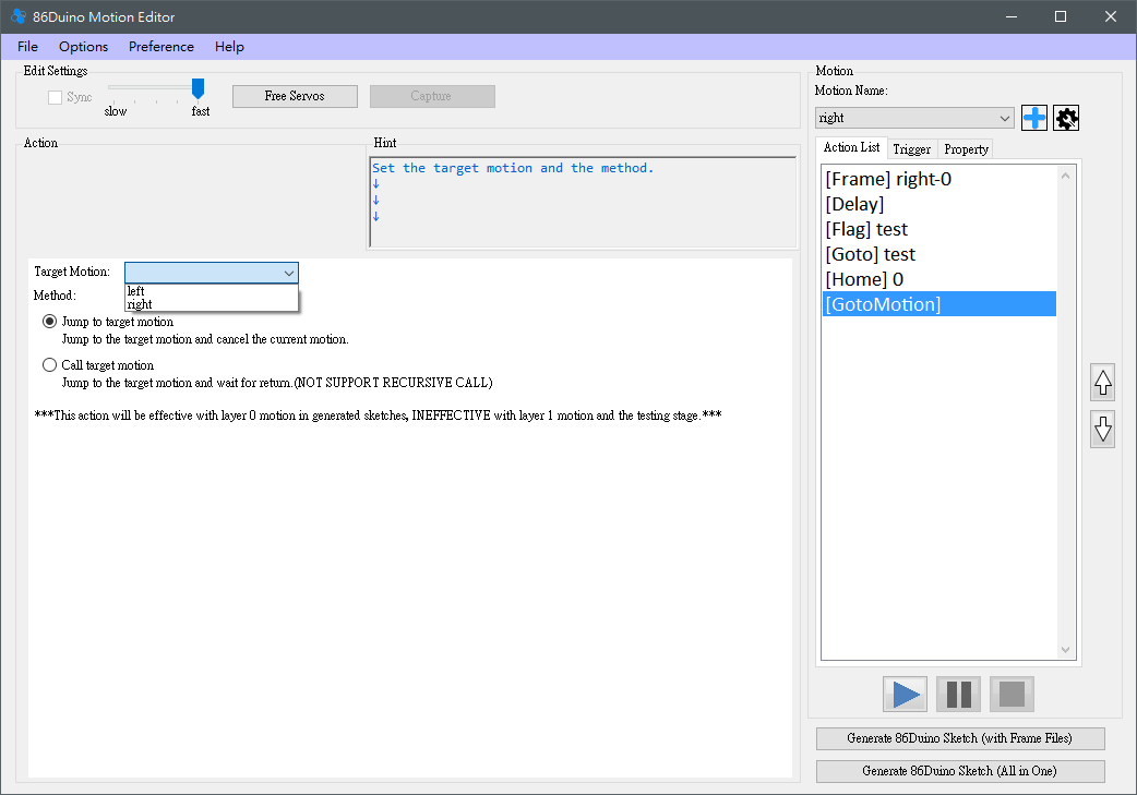
 GotoMotion
GotoMotion allows the robot to easily control other motion functions. Simply set the target motion and method. However, GotoMotion only reflects the generated program and does not currently support testing using the 86ME playback function.
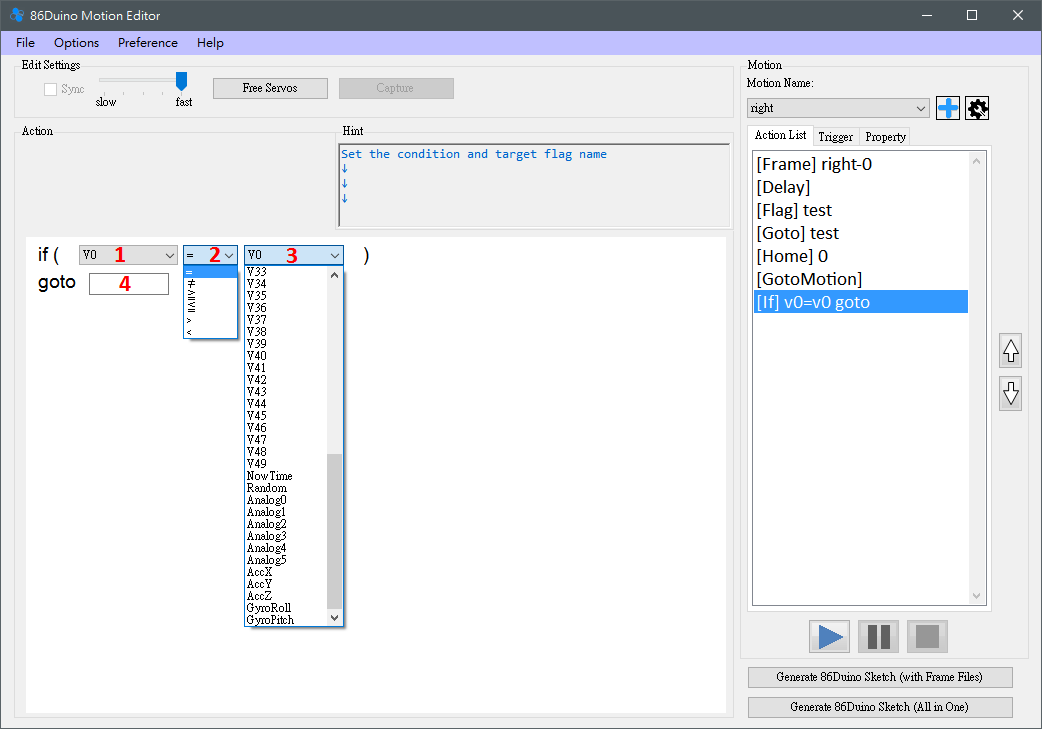
 If
IfIf provides flexibility in action editing. Currently, 50 variables and several useful system variables are available for user use. Simply set the condition to meet, and the action will go to the specified flag.
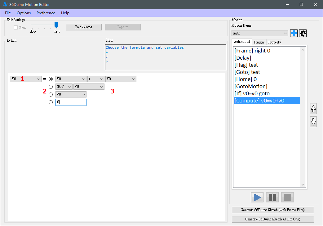
 Compute
Compute can be used to perform simple calculations and store the values in specified variables (V0-V49).
 Release
When the Release action is executed, all servos will stop outputting power. This action requires no configuration and will immediately take effect. It can be used when the robot is about to encounter danger (such as falling) to prevent the motors from being damaged by excessive force.
Step 5:
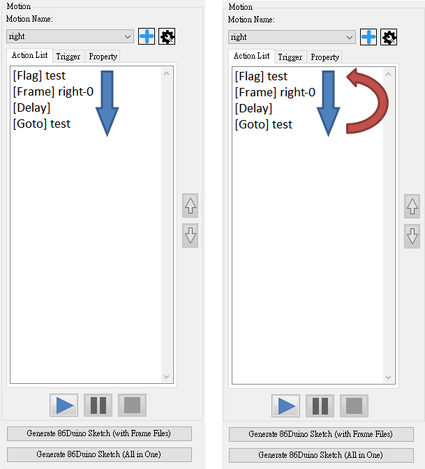
After editing your desired action, you can test it using the Play, Pause, and Stop buttons. The general execution sequence is shown in the lower left image. For Goto actions, the sequence is shown in the lower right image.
Next, users can choose to continue editing a different project (return to step 2), or a differentaction (return to step 3). Alternatively, select Save Project (File->Save Project) to generate a .rbm file. The next time you select Load Project, you can continue to use the previously saved project.
Adding an Image:
This feature allows users to easily map motors, eliminating the need to remember which motors correspond to which robot positions each time you load a project. You can add a robot image when creating a new project (File->New Project) or modifying the project configuration (Options->Robot Configuration). Use the Load Robot Picture button to load a PNG, JPG, or GIF file as the robot image. Once loaded, it cannot be removed. Once configured, Frame-type actions in the Action List can freely move the motors, achieving the desired alignment between the motors and robot parts.
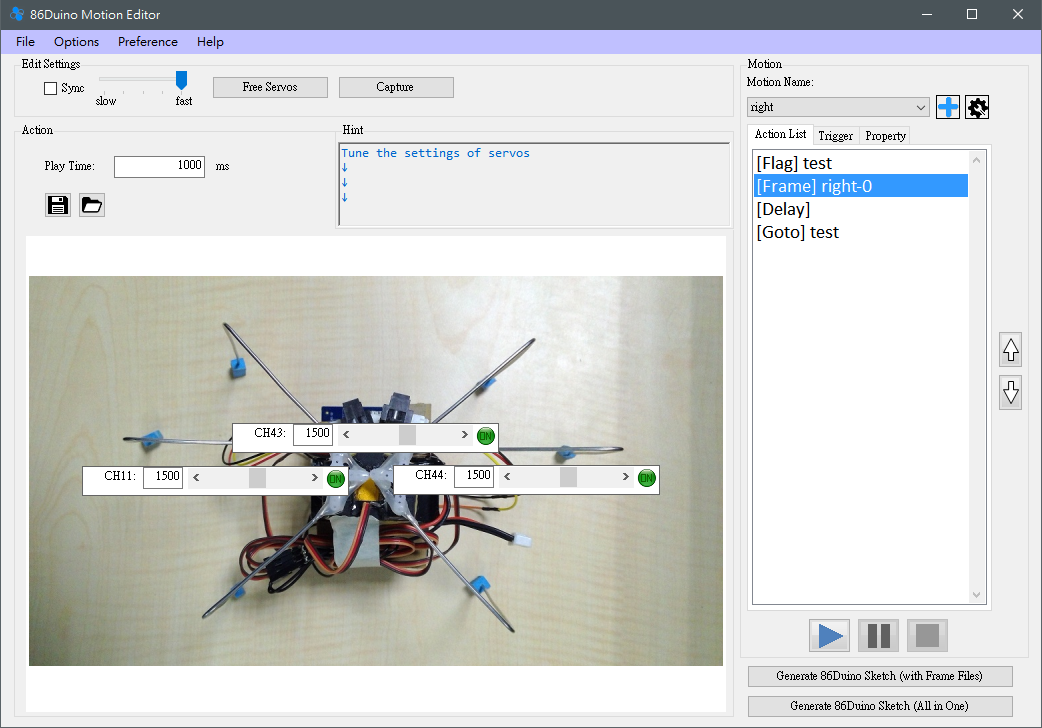
If you save an image after loading it, the saved .rbm file will remember the image's path on your computer. Therefore, if the image's location is changed or removed, it may not be found the next time you load the project. Please be aware of this!
Source Code
86ME is an open-source action editor. The source code is available on GitHub. Interested parties are welcome to download or share. This project was built on Windows 7/10 with Visual Studio 2013 Community Edition.
