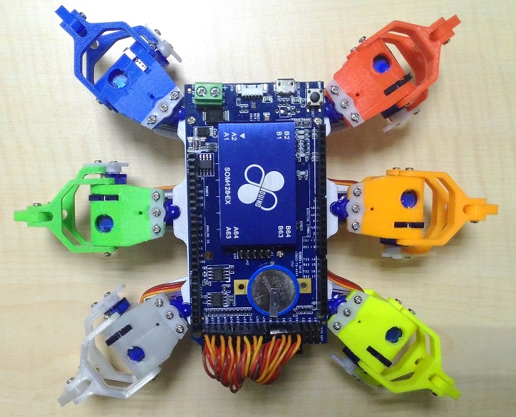
86Hexapod
Origin of the project
"Well… After the Scarna project, I really want to make a cute six-legged robot…" Perhaps it was because the previous Sgarna project successfully attracted widespread attention and discussion, which triggered the Maker soul in the boss. Since then, whenever he had a free time at work, the boss would think about how to expand the impact of robots on the education market. Now the idea is how to let everyone assemble one by themselves… Suddenly, "That's right! We have a 3D printer, Printer!" The boss suddenly had an idea. "Dr. Enzhuo, get ready!" "Huh? What…" Dr. Enzhuo was in a state of cuteness, but the boss ignored him and slapped a piece of paper on the table. Dr. Enzhuo took a look and saw that the paper said: Taiwan Beer, barbecue skewers. "What is this?" "Don't be in a daze, go and prepare these two things, I plan to use them to exchange for the design of the new six-legged robot!" "Could it be… to invite the legendary U University!?" Dr. Enzhuo suddenly understood. "That's right, if these are not enough, we will add more!!" The boss's eyes were full of stars. The Maker soul in his heart was ready to move. Just like that, after some lobbying (bribing), the world's first 86 hexapod was born under the ingenious design of U University.
Functional Description
86Duino 3D Printing Hexapod!! From the mechanism diagram to the program code, it is completely open source. You can download the files at home, match it with a 3D printer and teaching, and satisfy your desire for hand-made. You can make the motor move without writing a program. Use the open source 86ME motion editing software to complete the 86 hexapod's walking, turning, dancing and other movements, giving the 86 hexapod a strong vitality. Everything starts from scratch. The detailed steps are all in the teaching content below. If you are a strong hand-made person, why not prepare the materials and make a wave! !
Prepare materials
- One 86Duino One or 86Duino Zero motherboard (either one)
- 12 Tower Pro SG90 servos (if it is the first time to implement, it is recommended to buy 2 more as backup, that is, 14)
- One 3D printer (this project uses 86Duino ENJOY) . Auxiliary tools: file, needle-nosed pliers
- 1 pack of 2mm x 4mm screws (more than 20 pieces) 1 pack of 2mm x 8mm screws (more than 20 pieces) 1 pack of 2mm x 15mm screws (more than 20 pieces) . Assembly tools: screwdriver, 2mm tapping knife, 2mm drilling knife
- One electronic expansion board (only required when using 86Duino Zero, you need to make it yourself, click here for details) . One perforated board, 3 3×4 DuPont pins and 1 1×2 DuPont pin . Welding tools: soldering iron, solder
- 12 2.54mm DuPont wires
After preparing the materials, let's move our hands and stretch our muscles and start working! ! Oh my! Oh my! ! (Meaningless shouting)
Printing mechanism
The 3D printer we use here is 86Duino Enjoy. First, you need to download and install 86DuinoRepetier-Host, then follow the 86Duino Enjoy Quick Start Manual to set up the software and adjust the mechanical parameters of 86Duino Enjoy. Then you can go to the Thingiverse website to download 86 Little Six Legs STL Files ~ After decompressing the downloaded files, there are 6 files: 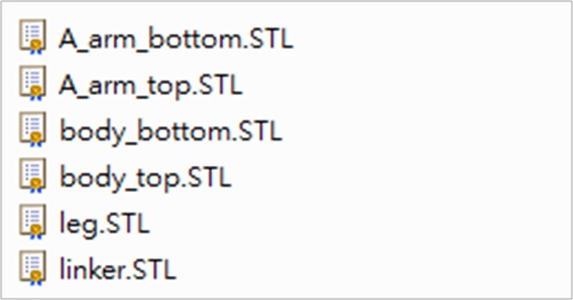
The file names of these 6 files correspond to the parts of the 86 Hexapod, as shown below: 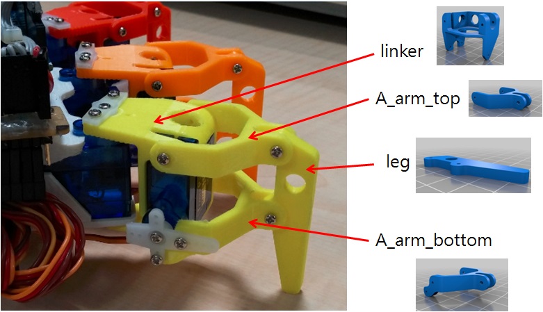
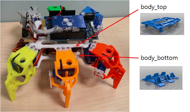 The first 4 parts: A_arm_bottom, A_arm_top, leg, linker, are all parts of the hexapod. Once all are printed, they can be combined into a leg (i.e. 1/6 of the number of legs). Just repeat the printing 6 times, and you will have 6 legs of the hexapod. Then the body_top part: the upper part of the hexapod body. Then the body_bottom part: the lower part of the hexapod body. Combining the above 2 parts can complete the hexapod body, and finally connect the 6 legs, and the 86 hexapod is complete. Let's first look at how to print parts using 86Duino Enjoy! Open the 86DuinoRepetier-Host that we have installed and click the Load button to load the four 86DuinoRepetier foot files: A_arm_bottom, A_arm_top, leg, and linker.
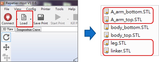
The loaded image is as follows: 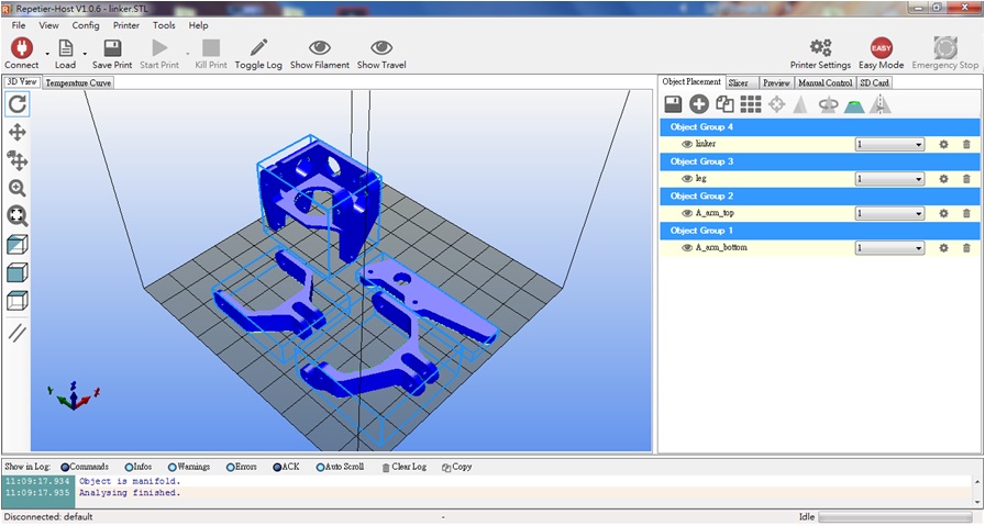 Click Linker and flip the part 90 degrees along the Y axis, as shown below:
 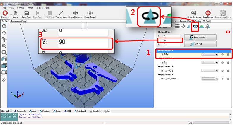 After flipping the linker part, the placement angle should be as shown below:
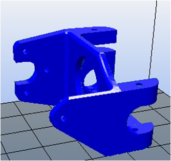
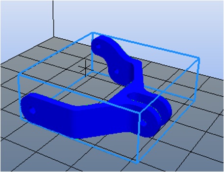
Click A_arm_bottom and flip the part 180 degrees along the Y axis, as shown below: 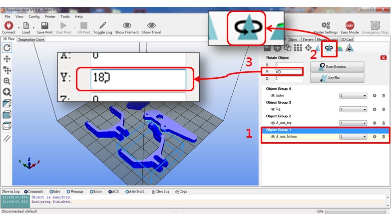 After flipping over, the A_arm_bottom part should be placed at the angle shown below:
After flipping over, the foot part is as shown below: Open the support option and set Support Type to Everywhere: 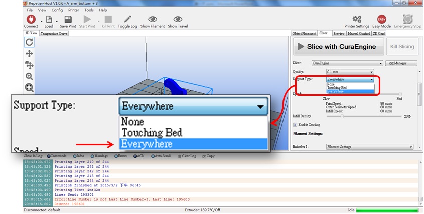 Coming here, we have gone through 2 processes in total:
1. Flip the part
2. Open support
Many people are confused here, why do we do this?
First of all, we know that this 3D printer uses a process called "fused lamination" The printing method is to heat the nozzle to melt the printing material, and then squeeze the printing material out of the nozzle. The hot printing material will quickly cool and harden when it encounters cold air. As the nozzle goes through all the paths, the cooled layer forms a hard plane, and then the nozzle is pulled up (or the part seat is lowered) to allow the second layer to continue to accumulate. This is the process. After printing one layer, the nozzle is pulled up, and after printing one layer, the nozzle is pulled up again, and this is repeated until the top layer of the part is "printed".
We know that parts are not always a solid cube. If they are, it would be easy to print successfully, huh? Can printing fail? That's right, if you don't understand the printing process, the chance of failure is quite high. Let's take a look at the things you must pay attention to when using this type of printer, and you will know why we need to flip the parts and open the support:
Like the linker part we saw above, it is a porous irregular part. With the "fused lamination" printing method, it will definitely print "certain paths" in a layer that happen to have no support from the previous layer (that is, the path is suspended below, which may be a hole!), so when the nozzle passes through these paths, the printed material will not have time to cool down and will be pulled down by gravity, which will make the appearance ugly at the least, and the whole part cannot be formed at the worst. It seems understandable that the appearance is ugly, but what is the method that makes it so serious that it cannot be formed?
The key is whether the suspended layer can form a stable plane. Once it cannot form a stable plane, all the layers above it will naturally have no bottom. Then the printed material will fall from the nozzle and cool directly in the air (because there is no bottom). As the nozzle moves, messy lines will form in the air. In the end, we get a bunch of lines instead of complete parts, which not only wastes time but also wastes printing materials.
In order to avoid such incidents, we flip the parts to make the suspended path of each layer of the parts shortest or even completely non-existent. This not only improves the success rate, but also improves the appearance of the finished product. After all, our parts are not solid cubes.
What if you can't find a suitable angle no matter how you flip it?
At this time, we can turn on the "Support" option of the software to let the software generate support parts by itself, so that those suspended areas have a bottom. After printing is completed, we can manually remove these support parts. Although there are more removal steps later, it is better than printing failure!
Seeing this, some people who are using 3D printers for the first time asked, if I don't consider the placement angle, can I directly turn on the "Support" option in the software? To be honest, yes, it is possible, this is the most time-saving and you don't have to consider how to flip, right? Anyway, the software automatically generates supports, so there is no need to worry about printing failure, just turn it on!
From the results, this idea may be correct, but we cannot control where the software generates supports and how many supports it generates. The software can only generate them arbitrarily according to its algorithm, which may cause you to fall into the hell of removing supports after printing (because too many supports are generated), especially supports in narrow gaps. It is difficult to remove them quickly. After finally removing them, there are still residues on the edges, which affects assembly, so you use a file to smooth them out… Too many supports always make us angry when removing them later. If you don't want to go through this "grinding" difficulty, it is recommended to turn the part over several times and actively find the angle that makes the supports produce the least (on the one hand, it also saves printing materials).
Some people say that they like the feeling of removing supports… It sounds very cool, so we don't object to choosing this method (you know, the process always hides the Maker spirit of some people).
The above is my experience of playing with this type of 3D printer. Whether you have read the long description or not, the next step is to press the slice button. The software will automatically add the parts it thinks should be supported, and finally generate a G-code file, which is a file that the 86Duino Enjoy printer can understand. 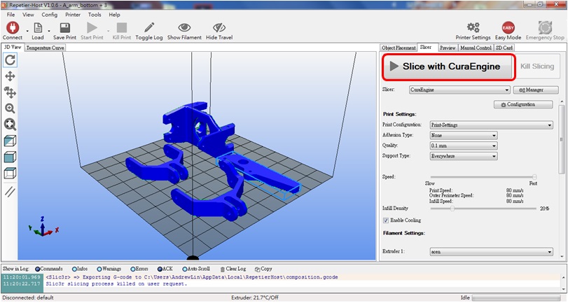 After completion, a screen similar to the following will appear:
 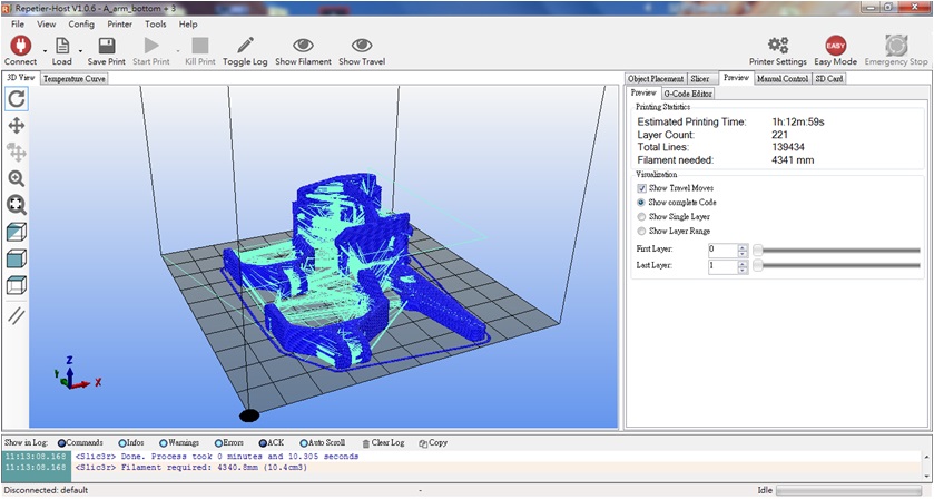 Now you are ready to transfer the file to 86Duino Enjoy~ There are two ways to transfer:
Method 1: Use USB cable to transfer
After slicing, connect the USB cable, and then press the print button, 86Duino Enjoy will start printing immediately: 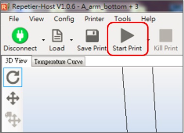
Method 2: Use SD card
Insert the SD card into your computer, After slicing, click the icon below to save the G-code file to the SD card: Select the G-Code Editor tab > Press the Save button 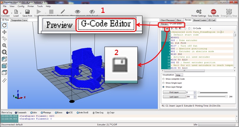 Save the file in the gcode folder on the SD card, change the file name to auto.gcode, and click Save.
 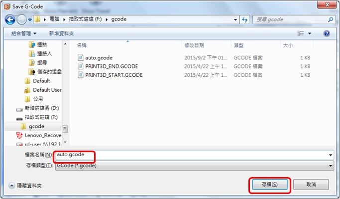 Unplug the SD card from the computer and insert it into the SD card slot on the back of 86Duino Enjoy.
Turn on the 86Duino Enjoy, and the 86Duino Enjoy will automatically read the auto.gcode file and start printing!
To complete a whole 86 small six-legged animal, you need to print the following:
1. 6 feet
2. 1 upper body
3. 1 lower body
The printing process may take a long time. You can have a cup of coffee, take a break, and wait until all parts are printed before moving on to the next step.
Assemble parts
There are many supports on the newly printed parts, and we must remove them first: Linker parts, use needle-nosed pliers to remove the following supports: 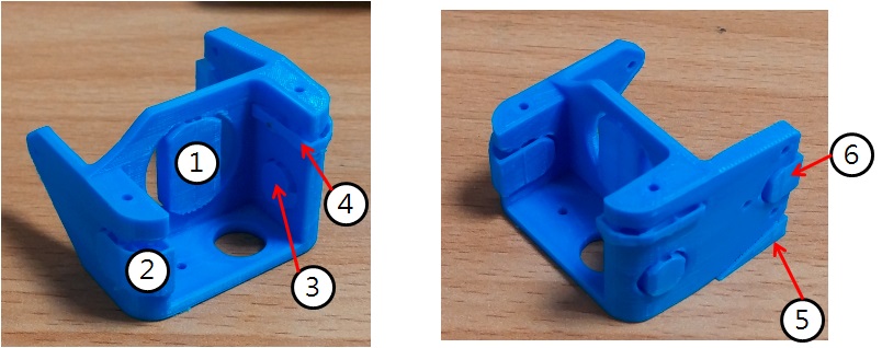 Body_top parts, use needle-nosed pliers to remove the following supports:
 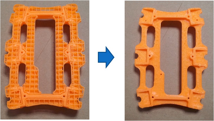 After the support is removed, you will find that there are still some burrs (bumps) left on the removed surface, which is not conducive to the subsequent assembly, so we pick up the flat file at hand and smooth these burrs. For the linker part, use a flat file to smooth the uneven surface (arrow in the picture below):
 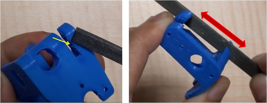 Grind until the servo can be smoothly placed:
 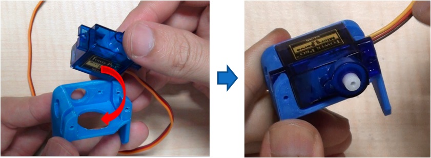 The same is true for the body_top part. Grind until the servo can be easily placed:
 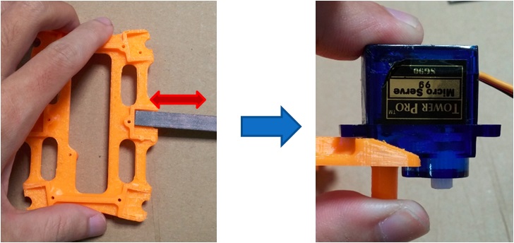 Finally, the body_bottom part is polished until the servo can be pressed in smoothly:
 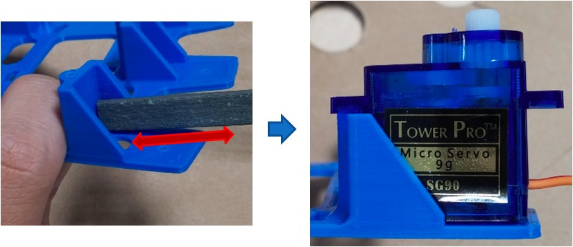 Can we start assembling next? Don't worry, we still need to drill and tap:
The holes that need tapping are shown in the red circle in the figure below:
Linker parts: 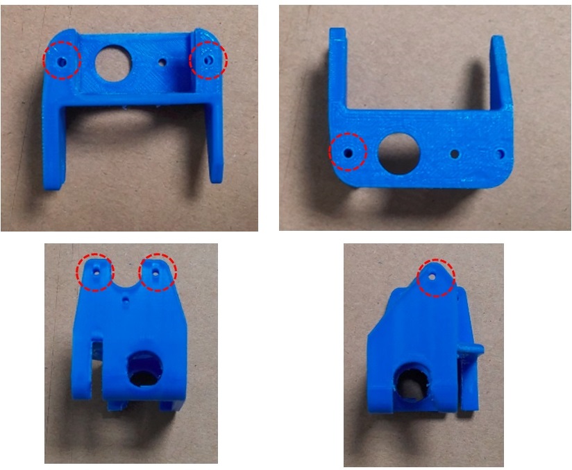 A_arm_bottom, leg parts:
 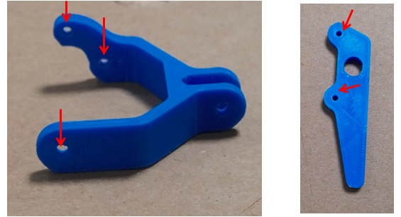 body_top, body_bottom parts:
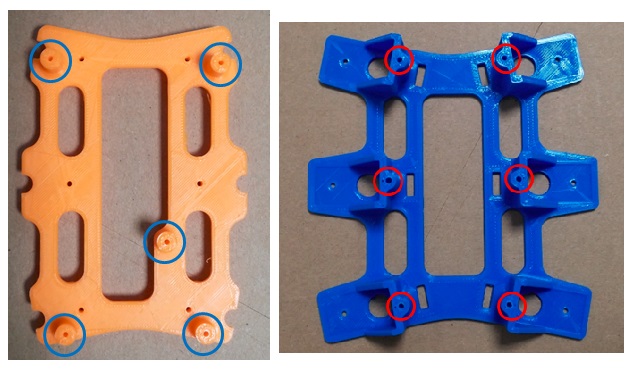
The holes that need to be drilled are as shown in the red circle in the figure below:
Linker, A_arm_bottom, A_arm_top parts: 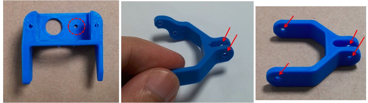 body_top, body_bottom parts:
 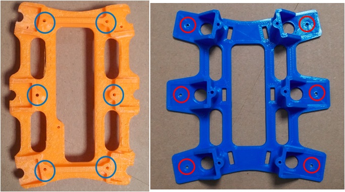 After completion, we can prepare to install the turntable on the servo, but we must first reset the servo to zero. Zeroing means turning the servo to the center of its movable range. We use the Servo86 library to reset the servo to zero, and use Servo86 to reset the servo to zero, and use 86Duino IDE Burn the reset program to the 86Duino development board. The following sample code is provided:
86Duino Zero reset program
|
1 2 3 4 5 6 7 8 9 10 11 12 13 14 |
|
86Duino One reset program
|
1 2 3 4 5 6 7 8 9 10 11 12 13 14 |
|
After burning, 86Duino will immediately send out PWM with a duty of 1500us from the specified pin. Then we need to connect the servo to 86Duino.
After connecting 86Duino to power/battery, the servo will immediately turn to the midpoint position. At this time, align the short axis of the cross-shaped accessory plate with the midpoint (marked line) and put it on the servo output shaft, as shown in the figure below: 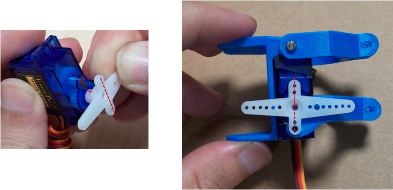 After completion, you can use screws to lock the parts. The final completed picture is as follows. You can also use diagonal pliers to modify the accessory plate and cut off the longer edges:
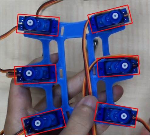
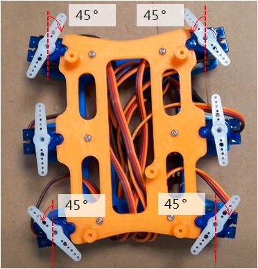
After completing the six legs, you can assemble the body and place the six servos in the body_bootom, as shown below:
Pull the servo connection lines that fall on the outside to the center of the body and extend them from one end (this is done to facilitate subsequent wiring): 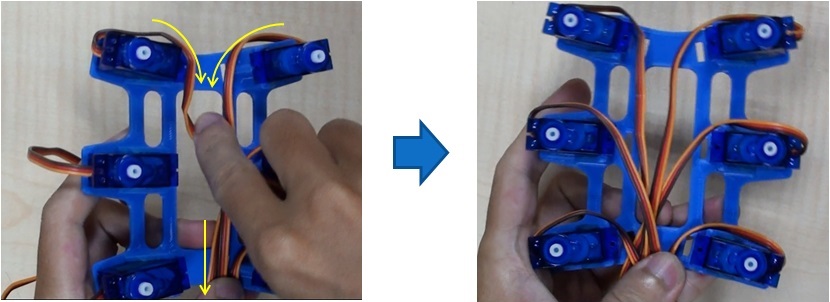 Cover the body_top part and tighten the body_top with 6 15mm screws, as shown in the red circle in the figure below:
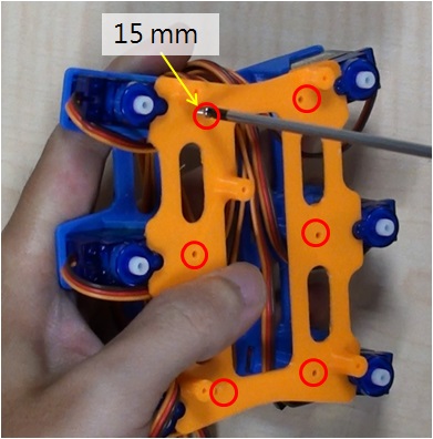
Use a drill to drill holes in the slotted accessory tray (the second hole from the center, as shown in the figure below). A total of 6 slotted accessory trays need to be drilled: 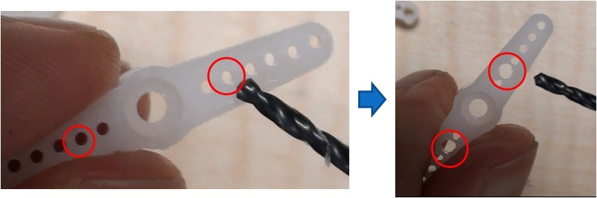 Use the zeroing program provided above to zero the six servos to the midpoint, and put the straight-shaped accessory plate onto the servo output shaft as shown below:
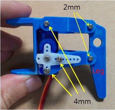
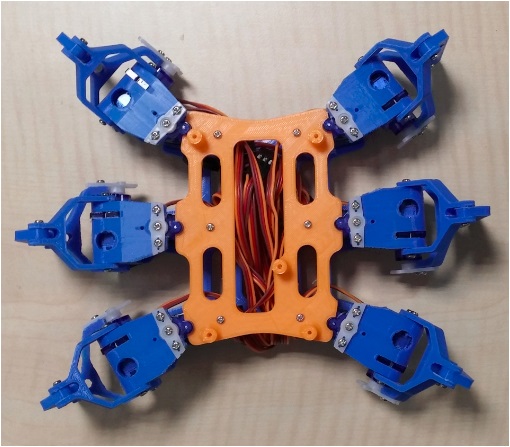
Use 3 2mm x 4mm screws to connect the foot (2 to fix the accessory plate, and the other to fix the linker and body_bottom), and use self-tapping screws to tighten the servo's slotted accessory plate. You can use diagonal pliers to cut off the protruding part of the slotted accessory plate to increase the appearance: 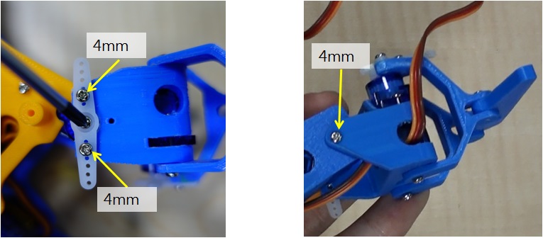 After all 6 feet are locked, it looks like the following figure:
Install 86Duino Zero Development Board
Corresponding to the red circle in the figure below, use 3 2mm x 4mm screws to fix 86DuinoZero on body_top: 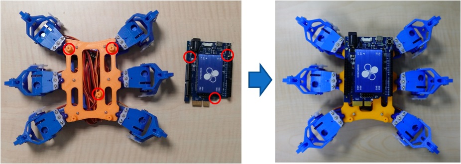 Use 2 2mm x 4mm screws to fix the expansion board:
 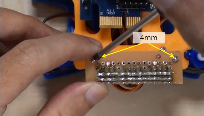 The 86 small hexapod servo numbers correspond to the pins on the expansion board as follows:
 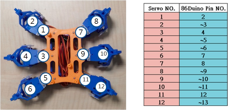 Use 12 yellow (PWM), 1 red (VIN), and 1 black (GND) Dupont wires to connect 86DuinoZero and adapter board:
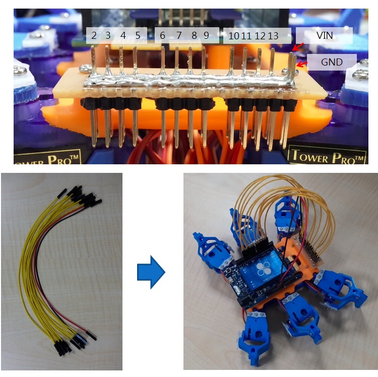
Install the 86Duino One development board
Corresponding to the red circle in the figure below, use 3 2mm x 4mm screws to fix the 86DuinoOne to the body_top part: 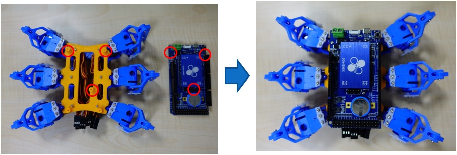 The 86 hexapod servo numbers correspond to the pins on the 86DuinoOne as follows:
 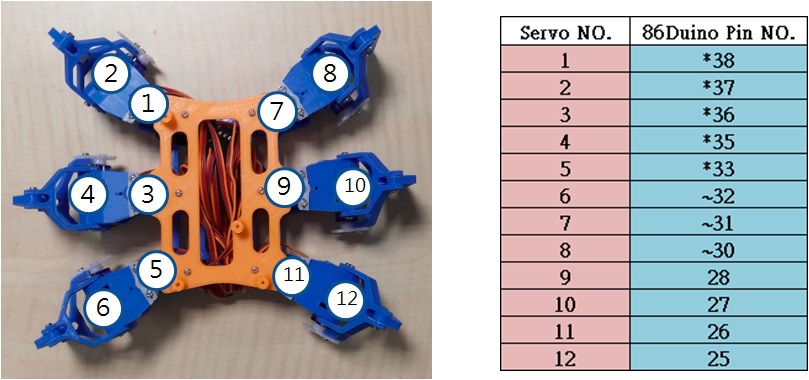 Connect all servo cables to the 86DuinoOne:
 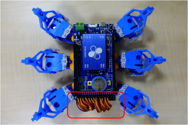 Finally, we will tidy up the exposed cables to make the 86 hexapod look more beautiful. First, pull the exposed servo cables into the body of the 86 hexapod, fold the servo cables back and forth, and fix them to the brackets on both sides with cable ties:
 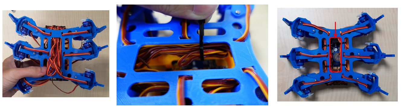 After fixing with cable ties, try to avoid servo cables passing through the red frame in the right picture, because this is the space for placing lithium batteries in the future.
Motion Control
Since 86ME Mk-II has set the 86 Hexapod application project as an example project, you can find the walking action of 86Hexapod.rbm in C:\ProgramData\86ME\examples. After opening the project, remember to fine-tune its offset value according to each 86 Hexapod, which can correct some small errors on the servo.
Results display
— DEMO video —
Related information
[2] STL structure file download
[3] 86 small six-legged robot DIY course materials:
Homemade Amusement Park Home Page
The text of the 86Duino reference material follows the Creative Commons Attribution-Share Alike 3.0 License. The code examples in the reference material have been released to the public domain.