SPI library
This library allows you to communicate with SPI devices, with the 86Duino as the master device.
A Brief Introduction to the Serial Peripheral Interface (SPI)
Serial Peripheral Interface (SPI) is a synchronous serial data protocol used by microcontrollers for communicating with one or more peripheral devices quickly over short distances. It can also be used for communication between two microcontrollers.
With an SPI connection there is always one master device (usually a microcontroller) which controls the peripheral devices. Typically there are three lines common to all the devices:
- MISO (Master In Slave Out) – The Slave line for sending data to the master,
- MOSI (Master Out Slave In) – The Master line for sending data to the peripherals,
- SCK (Serial Clock) – The clock pulses which synchronize data transmission generated by the master,
and one line specific for every device:
- SS (Slave Select) – the pin on each device that the master can use to enable and disable specific devices.
When a device’s Slave Select pin is low, it communicates with the master. When it’s high, it ignores the master. This allows you to have multiple SPI devices sharing the same MISO, MOSI, and SCK lines.
To write code for a new SPI device you need to note a few things:
- Is data shifted in Most Significant Bit (MSB) or Least Significant Bit (LSB) first? This is controlled by the
SPI.setBitOrder()function. - Is the data clock idle when high or low? Are samples on the rising or falling edge of clock pulses? These modes are controlled by the
SPI.setDataMode()function. - What speed is the SPI running at? This is controlled by the
SPI.setClockDivider()function.
The SPI standard is loose and each device implements it a little differently. This means you have to pay special attention to the device’s datasheet when writing your code.
Generally speaking, there are four modes of transmission. These modes control whether data is shifted in and out on the rising or falling edge of the data clock signal (called the clock phase), and whether the clock is idle when high or low (called the clock polarity). The four modes combine polarity and phase according to this table:
| Mode | Clock Polarity (CPOL) | Clock Phase (CPHA) |
SPI_MODE0 |
0 | 0 |
SPI_MODE1 |
0 | 1 |
SPI_MODE2 |
1 | 0 |
SPI_MODE3 |
1 | 1 |
The SPI.setDataMode() function lets you set the mode to control clock polarity and phase.
Every SPI device has a maximum allowed speed for SPI Bus. The SPI.setClockDivider() allows you to change the clock speed to make your device working properly.
Once you have your SPI parameters set correctly you just need to figure which registers in your device control which functions, and you’re good to go. This will be explained in the data sheet for your device.
For more on SPI, see Wikipedia’s page on SPI.
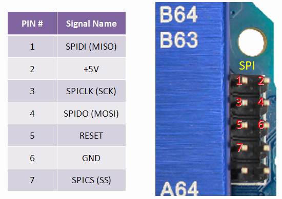
Connections
The following table display on which pins the SPI lines are broken out on the different 86Duino boards:
| 86Duino Board | MOSI | MISO | SCK | SS |
| Zero | SPIDO | SPIDI | SPICLK | SPICS |
| One | SPIDO | SPIDI | SPICLK | SPICS |
| Educake | – | – | – | – |
Note that MISO, MOSI, SCK, and SS are available in a consistent physical location on the SPI header; this is useful, for example, in designing a shield that works on every board.
Functions
- begin()
- end()
- setBitOrder()
- setClockDivider()
- setDataMode()
- setSS()
- transfer()
Examples
The following are examples of the SPI library from the Arduino Tutorial that can work on the 86Duino boards (but, when you refer to the circuits in these examples, note that the location of 86Duino’s SPI pins is different from the Arduino boards adopted in these examples):
- BarometricPressureSensor: Read air pressure and temperature from a sensor using SPI
- SPIDigitalPot: Control a digital potentiometer using SPI
See also
- shiftOut()
- shiftIn()
The text of the 86Duino reference is a modification of the Arduino reference, and is licensed under a Creative Commons Attribution-ShareAlike 3.0 License. Code samples in the reference are released into the public domain.