86Duino One Hardware Introduction
Introduction
86Duino-One is an open-source microcomputer learning platform built on Vortex86EX, a System-On-Chip (SoC) built with 32-bit x86 processor. It’s designed to be electronically compatible to the Arduino platform. In addition, all 86Duino platform includes Arduino emulation software which enables application codes written for Arduino (sketch) to be compiled and run on the 86Duino platform without modification.
In a nutshell, the 86Duino platform is hardware and software compatible to the Arduino platform.
The 86Duino-One board is designed with mix of I/O interfaces that support broad range of application, designed to simplify the task for developer to create automation and robotics application, which include support for up to 18 RC servos, RS-485, CAN-bus, 6 axis gyro and accelerometer and etc.
Designed to serve the DIY hobbyist community, 86Duino-One I/O interface is designed with protection circuity to minimize damages caused by transient, over voltage and reversed polarity.
Following is a list of the specification for the 86Duino-One:
- CPU: 300 MHz Vortex86EX System-on-Chip with a 32-bit x86 processor (CPU can be overclocked to 400MHz using SysImage)
- RAM: 128 MB / 1 GB industrial-grade DDR3 SDRAM
- Flash: 8 MB internal flash, preloaded with system BIOS and 86Duino firmware.
- 10/100 Mbps Ethernet via an RJ-45 connector
- 1 USB host interface
- 1 Micro-SD slot
- 1 Mini PCI-E interface
- Integrated Realtek ALC262 HD audio chip with 1 Audio output and 1 microphone input
- The 5V power input connector is a Type B micro USB female connector, which is also the interface to the development computer to upload application code (sketch) from the 86Duino Coding IDE.
- 6V to 24V power input through a terminal block connector.
- 45 digital I/O pins configurable to serve multiple function, which include 18 RC servo output.
- 3 TTL UART (Serial interface)
- 1 RS-485 serial interface.
- 4 Encoder interfaces.
- 7 A/D input pins
- 11 PWM output pins
- 1 SPI interface
- 1 I2C interface
- 1 CAN Bus interface
- 3 axis gyro
- 3 axis accelerometer
- System reset
- Dimension: 101.6mm x 53.34mm
- Weight: 56g
I/O Interfaces Layout
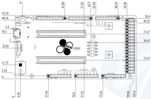
Mechanical dimension
Mechanical dimension for 86Duino-One is similar to the Arduino Mega 2560, as shown in the following figure:(full size Mechanical dimension )
Mounting holes for 86Duino-One are in the same location as Arduino Mega 2560 and Arduino Leonardo, as shown below:

I/O Interfaces Pin-out
As shown in the following pin-out diagram for 86Duino-One, the top half portion of the pins are designed to be compatible to the Arduino platform.
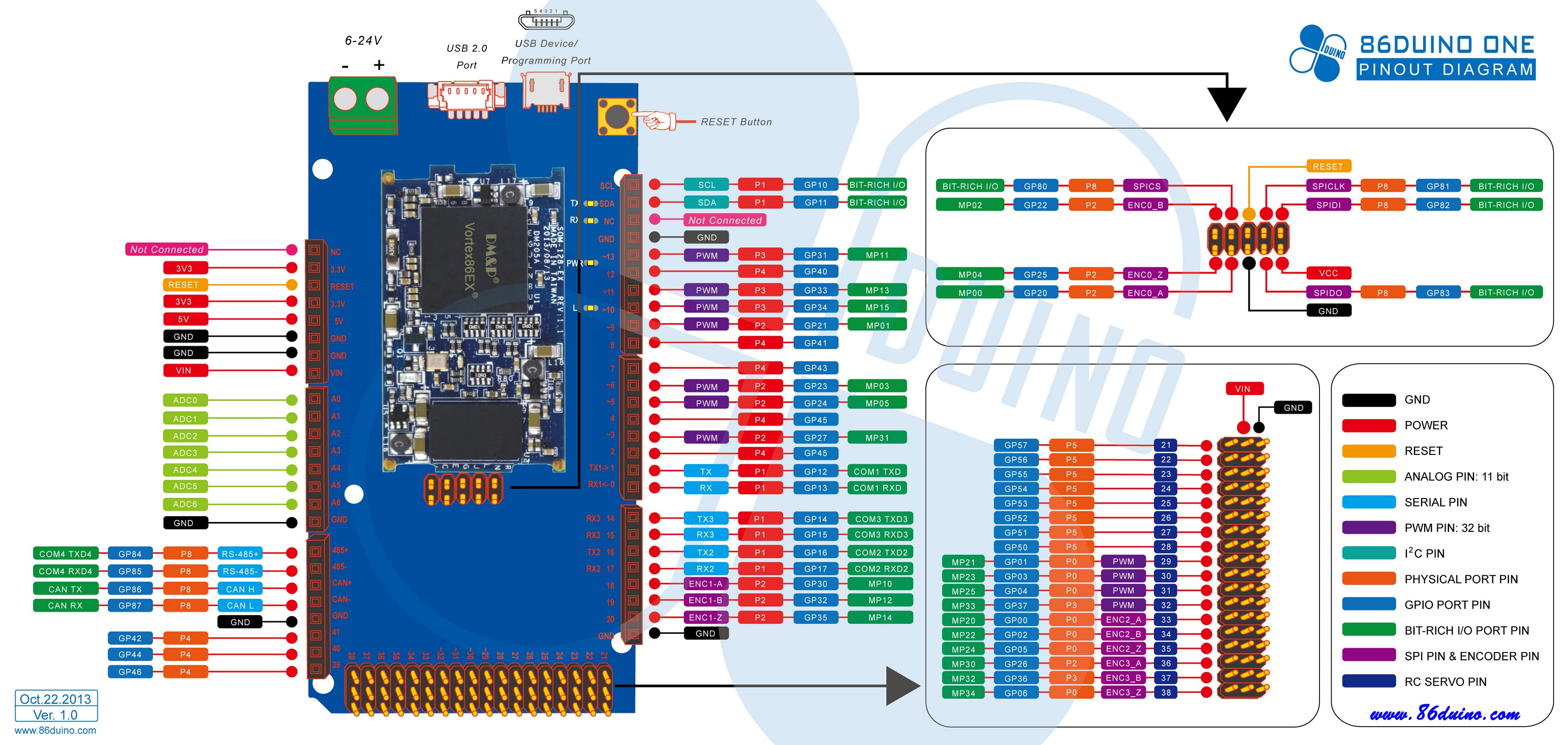
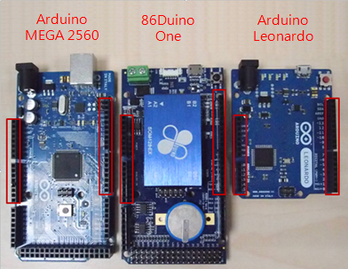
As indicated in the following figure, showing 86Duino-One alongside an Arduino MEGA 2560 and Leonardo, the pin-out headers marked in red are compatible. The pin-out on these header is also know as Arduino 1.0 pin-out. On the 86Duino-One board, the lower portion of the pin-out includes pins to interface with servos, which is different from the Arduino Mega 2560. 86Duino-One is able to support Arduino shield designed for Arduino Leonardo, such as the Arduino WiFi Shield, and not able to support shield designed for the Arduino Mega 2560, such as the RAMPS 1.4 shield.
I/O Interface Function and Feature
1. Power System
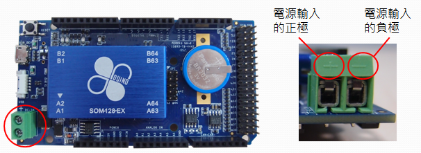
86Duino-One has two separate interfaces for power input. A terminal block connect that can support 6V to 24V power source, the green connector as shown in the following figure.
Another interface for power input is the Micro-USB connector, as shown in the following figure.
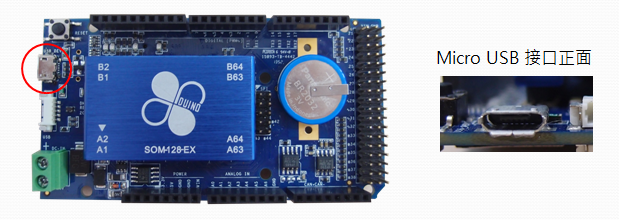
The 86Duino-One board can be powered by 5V power source from the Micro-USB connector. Or, 6 ~ 24V power source from the green terminal block connector. When power by the Micro-USB connector, the 5V power from the USB connector is applied to power the onboard circuitry. When using 6 ~ 24V power source from the terminal block to power 86Duino-One, the power goes through the onboard power regulator circuitry that produce 5V power needed by the 86Duino circuitry.
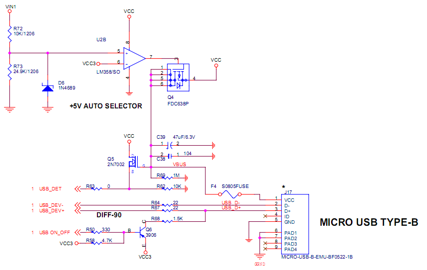
When power sources are attached to both the Micro-USB and terminal block connectors, the 86Duino-One includes circuitry to automatically select one of the stable power source to power the board, as shown in the following schematic:
Power input through the Terminal Block
The terminal block power input is designed to input higher current, where the excess current can be used to power externally attached peripherals, such as external device attached to the USB interface, servo and motors.
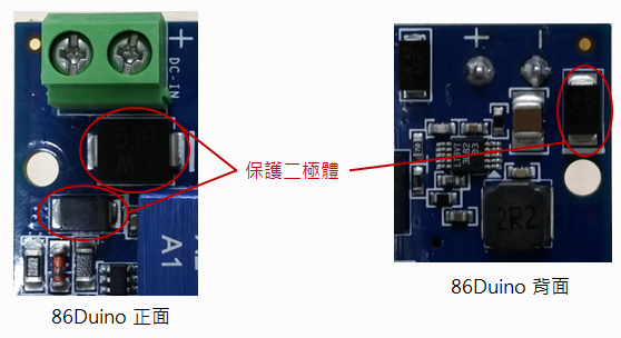
Transient Voltage Suppression (TVS) diodes are added to the voltage input circuit (Vin) to protect the board against surge and reversed polarity from damaging the board, as shown in the following schematic.
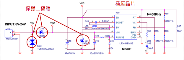
Note: The added protection circuitry on the 86Duino-One board is limited to protect against voltage within the 40V range. Higher voltage condition will damage the board.
Power 86Duino-On using Battery
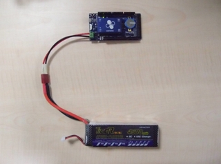
For robotics application, it’s common to use battery as power source. By connecting the battery power to the terminal block, as shown in the following figure, it can supply higher current than the Micro-USB, which is needed to power the robot’s servos and motors.
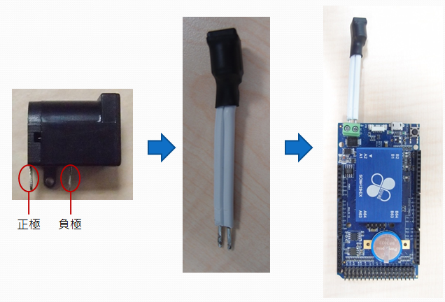
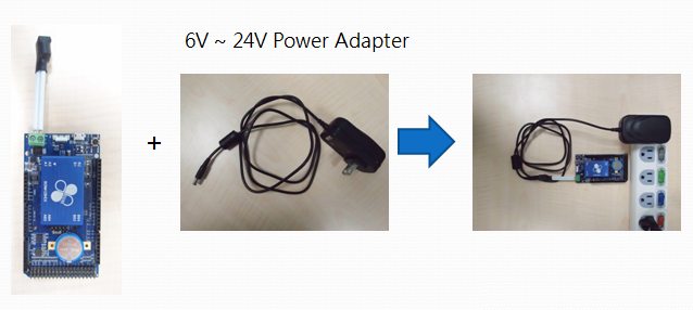
Power 86Duino-One using AC Power Transformer
There are broad range of AC to DC power transformer to power different type consumer electronic devices, which you may have. To use an AC to DC power transformer as power source, make sure the power output is within the range supported by 86Duino-One and make the connection with correct polarity. To use an AC to DC power transformer with a barrel plug, it’s best to use matching barrel power jack to attach to the terminal block connector on the 86Duino-One board and insert the barrel plug from the power transformer (make sure the polarity is correct), as shown in the following figures.
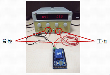
Power 86Duino-One using DC power supply
To DC power supply as power source for 86Duino-One, you simply connect power output from the power supply to the power input terminal block on the 86Duino-One, with matching polarity, as shown in the following figure:
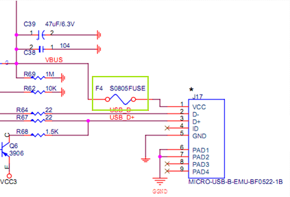
Power input through the Micro-USB interface
The 86Duino-One can get power from the Micro-USB interface, by connecting to an USB host interface designed to meet the required voltage and current output for an USB host. Or connect to an USB power source. The Micro-USB power input circuit on the 86Duino-One is designed some protection, inline one AMP fuse is added to the power circuit to protect the board from damage by over current, as shown in the following schematic.
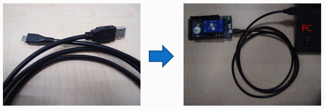
You can use a Micro-USB to Type A USB cable, which is a common power/charging cable for many of the smartphone in the market, to connect 86Duino-One to an USB port on a PC or laptop to get power, as shown in the following figure:
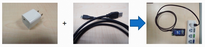
You can also use the same Micro-USB to Type A USB cable to get power from a smartphone charger, such as the one shown in the following figure.
When there are additional external device or peripheral attached to the 86Duino-One board, including device that draw power from the 5V or 3.3V output circuit, the required current will exceed the 500mA from an USB 2.0 interface. To support higher current requirement, you can consider getting power from an USB 3.0 interface, which is designed to supply up to 900mA of current. Or, use an USB power source with higher current, to support additional external USB devices attached to the 86Duino-One, where each of these USB device can draw 500mA of current.
Note: Without any external device attached, the 86Duino-One board requires 440mA at +5 V DC to function. A typical USB 2.0 interface on a PC or laptop is designed to supply up to 500mA at +5 V DC, which is sufficient to power the 86Duino-One board without additional peripheral connected.
Note: USB interface on some of the older legacy PC may not meet the USB design specification and may not be able to supply the 500mA current needed to power the 86Duino-One board. In the event the 86Duino-One board fails to boot up as expected, be sure to check and make sure the power source is capable to supply the required current to power the 86Duino-One board and attached peripherals.
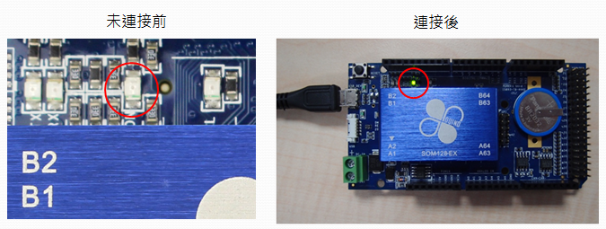
LED Power Indicator
The Micro-USB power input circuit includes a green LED that function as status indicator. When proper power is detected, the green LED will turn on, as shown in the following figure:
Power Output Pins
There are multiple power output pins on the 86Duino-One board to power external devices, which includes 3.3V, 5V and Vin, as shown in the following figure:
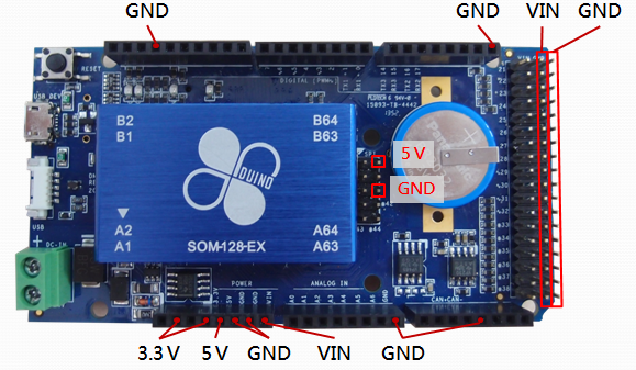
The 3.3V and 5V output pins can be used as power source for external circuit and shield. The 3.3V pin is capable to output up to 400mA. The 5V pin is capable to output up to 1000mA. The Vin pin is directly connected to the green terminal block’s positive (+) input, which can be used to provide power source to support servo and motor that require higher current.
Note: When working with external circuit that require higher current above 1A, avoid using the 3.3V and 5V as power source, use Vin instead. When using Vin with a higher voltage, avoid shorting Vin to the other pins to prevent damage to the internal circuit and components.
2. MiroSD Slot
The MicroSD slot on 86Duino-One is designed to support up to 32GB SDHC flash storage card. SDXC is not supported.
When launching Windows or Linux operating system from MicroSD, the MicroSD flash storage’s performance directly impact the operating system’s boot up time and execution speed. It’s best to use Class 10 MicroSD storage card.
The SysImage utility is provided to configure and place 86Duino firmware onto a MicroSD storage card, enabling 86Duino-One to launch the 86Duino firmware from the MicroSD storage card, which has a certain advantage. For more information, refer to the following URL.
Boot Sequence
When power-on, after hardware initialized, 86Duino-One BIOS looks for bootable storage device in the following sequence:
1. MicroSD flash storage
2. USB flash storage – When MicroSD flash storage is not present, 86Duino-One boot from USB flash storage.
3. Internal built-in flash – When both MicroSD and USB flash storage are not available, 86Duino-One boot from the internal flash storage.
Note: When non-bootable MicroSD or USB flash storage is present, the 86Duino-One will attempt to boot from the detected MicroSD or USB flash storage, instead of the internal flash storage. Since the MicroSD or USB flash storage is non-bootable, the boot process will fail.
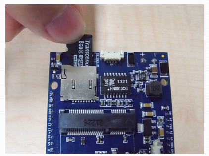
MicroSD flash storage insertion direction
When using MicroSD storage, be certain to insert the MicroSD flash storage card in the correct direction, as shown in the following figure:
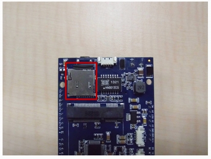
The MicroSD slot is place further away from the edge of the PCB by design. When a MicroSD card is inserted to the slot, the edge of the MicroSD card does not extend beyond the edge of the PCB, as shown in the following figure. The MicroSD slot location is a robotics application design consideration, to keep inserted MicroSD flash card away from the edge of the PCB to avoid being bumped accidently by other robots or as the robots move around, which can dismount or damage the inserted MicroSD card.
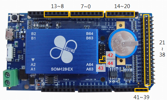
3. GPIO Pins (Digital Input and Output)
There are 45 GPIO pins on the 86Duino-One, as shown in the following figure. From the 86Duino Coding development environment, you can call the digitalWrite() function to control voltage HIGH or LOW condition on these pins, and call digitalRead() function to read the status for each of these pins.
Each of the GPIO can function as input or output. You can call the pinMode() function to configure each of the GPIO pins to function as input or output. When configured to function as output, each of these GPIO pins output 3.3V when set to HIGH and output 0V when set to LOW. Each pin is capable to output up to 16mA of current. When a GPIO pin is configured to function as input, the working voltage range is 0~5V.
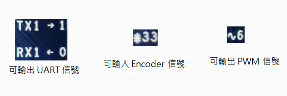
Similar to the Arduino platform, some of the GPIO pins can be configured with other function, such as PWM, UART with Rx and Tx and encoder input, with marking to indicate the pins’ capability, as shown in the following figures:
For more information about GPIO, refer to the following URL.
RC Servo Connector
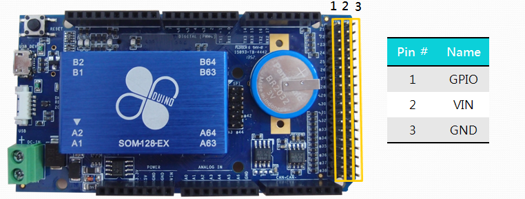
GPIO Pins 21 ~ 38 on the 86Duino-One are configurable to output PWM signal. The connector for GPIO Pins 21 ~ 38 on the 86Duino-One is designed to directly support RC servos, where there are GND and Vin pins for each of these PWM output capable pins as shown in the following figure.
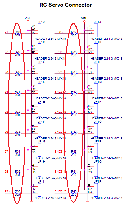
There are significant difference in quality for RC servo available in the market. As an added protection, a 200 ohm current limiting resistor is added to each of the PWM capable GPIO pin, as shown in the following schematic. The 86Duino-One board is designed to support robotics application that uses multiple or all of the 18 PWM capable output to drive servos, which quire higher current. The 86Duino-One board is designed to handle up to 10A of current.
Note: RC Servo interface and connector do not include protection circuitry. Vin and GPIO pins are positioned closely next to each other on the connector. Extreme care is needed to avoid short between these two pins, which can cause permanent damage to the GPIO pin. In addition, Vin pins also should not be connected with any 86Duino pins like 5V, 3.3V, CAN BUS, TX, RX, I2C or SPI, otherwise the high voltage of VIN will hurt those function pins.
RC Servo Connection
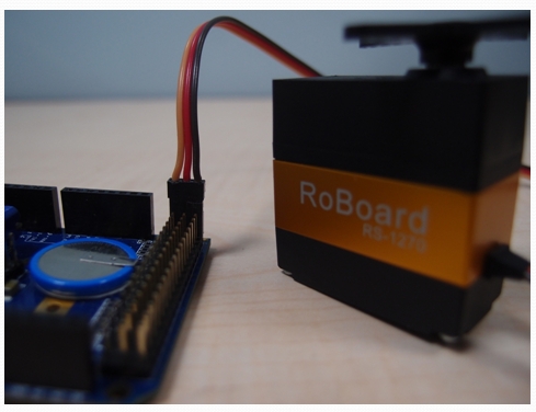
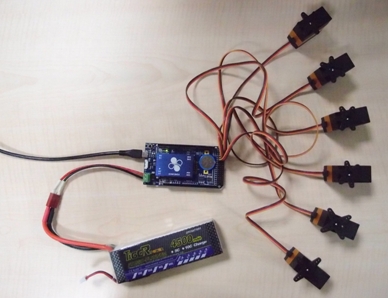
The connector with 3 rows of pins (18 pins each row) on the 86Duino-One is designed to support common RC Servo connector, where you can connect a RC Servo to the board, as shown in the following figure:
Some lower cost RC servo in the market are designed poorly and has the tendency to draw high current momentary during startup, causing voltage level on Vin to drop below 6V, which trigger the CPU module’s low voltage threshold causing the under-voltage protection to kick in and shut down the system. One of the way to fix this kind of problem is to use a power source that can sustain high current draw momentary, such as a higher capacity battery. Another option is to use the stable 5V power source from the Micro-USB interface to power the 86Duino board and use a separate power source through the terminal block power input to supply power to Vin to power the servo, as shown in the following figure:
4. LED Status Indicators
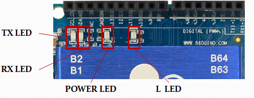
LED is a common status indicator for many product and is also frequently used during the development process as activities or process indicator for experiment and testing purposes. There are 4 LEDs on the 86Duino-One board (as shown in the following figure):
1. Power status LED
2. USB device data transmit activity status (Tx) LED
3. USB device data receive activity status (Rx) LED
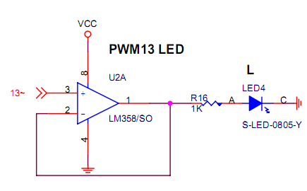
4. “L” LED (Can be controlled using GPIO pin #13)
When Pin 13 output HIGH, the “L” LED turns on. When Pin 13 output LOW, the “L” LED turns off. Following is the schematic showing the circuitry between Pin 13 and the “L” LED.
5. RESET
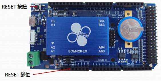
The 86Duino-One board is built with a system Reset button, on the corner of the board, next to the Micro-USB connector, as shown in the following figure:
The pin on the RESET button is linked to the CPU module’s reset circuitry. A low voltage pulse to the reset circuitry trigger the CPU to reset, as shown in the following circuitry:
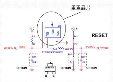
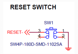
The reset circuitry is linked to the push button, when the button is pressed, it trigger the 86Duino-One board to restart, as shown in the following circuit:
6. A/D Pin
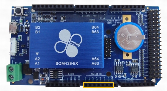
There are 7 A/D input pins on the 86Duino-One board, AD0 ~ AD6, as shown in the following figure:
Each of the A/D input is capable to handle up to 11-bit resolution. From the 86Duino Coding environment, you can call the analogRead() function to read the voltage level from these A/D pins. To be compatible with the Arduino platform, the analogRead() function is based on 10-bit resolution. To get 11-bit resolution, you can call the analogReadResolution() function.
Note: Each of the A/D input pin is designed to support 0V to 3.3V input. It’s important to keep the input voltage level below 3.3V for all of the A/D input pin. When input voltage for anyone of the A/D pin is above 3.3V, it will cause incorrect reading to all 7 A/D input channels, and may cause permenant damage to the board. Unlike the A/D pins on the Arduino Leonardo, the A/D pins on 86Duino-One cannot be switched to function as digital input and output pins.
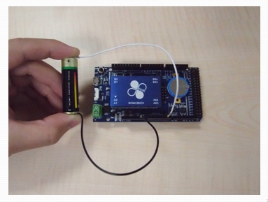
A/D Pin wiring example
In this wiring example, we will use an 86Duino-One board to check voltage level for an AA battery, by connecting the battery’s positive pole to one of the A/D pin (AD0 ~ AD6) and connect the battery’s negative pole to the board’s GND signal. Then, call the analogRead() function to read the battery’s voltage level, as shown in the following figure:
For more information about A/D input, refer to the following URL.
7. I²C Interface
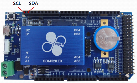
There is one I²C interface on the 86Duino-One, SDA and SCL, as shown in the following figure:
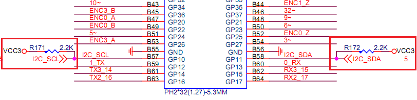
From the 86Duino Coding environment, you can use the Wire library to control the I²C interface, which can support standard mode (up to 100 Kbps), fast mode (up to 400 Kbps) and high speed mode (up to 3.3 Mbps) to communicate with external module with I²C interface. According to I²C design specification, to interface with external I²C device, pull up resistors need to be added to the SCL and SDA pins. The I²C interface on the 86Duino-One is built with 2.2K ohm pull up resistor, which is sufficient to support 100 Kbps and 400 Kbps data transfer speed. When working with higher transfer speed, such as 3.3 Mbps, it’s recommended to add 1.8K to 2K external pull up resistor.
I²C wiring example
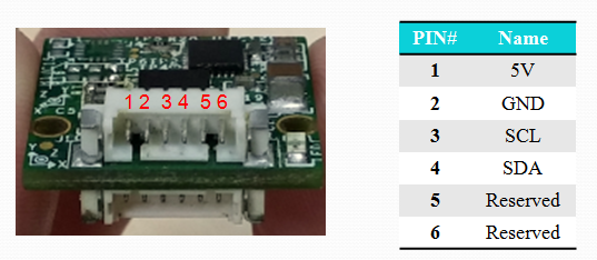
For this wiring example, we will connect a RoBoard RM-G146 module (with 3-axis magneto sensor, 3-axis accelerometer and 3-axis Gyro), built with an I²C interface to the 86Duino-One board, as shown in the following figure:
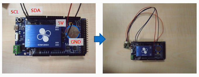
Since the I²C interface on 86Duino-One is built with internal pull up resistor, we can directly connect the 5V, GND and I²C pins from the RM-G146 module to the 86Duino-One board, as shown in the following figure:
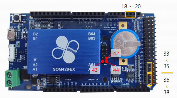
8. PWM Output
There are 11 GPIO pins on the 86Duino-One board capable to be configured as PWM output, pins 3, 5, 6, 9, 10, 11, 13, 29, 30, 31 and 32, as shown in the following figure:
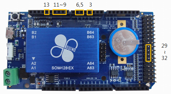
From the 86Duino Coding environment, you can call the analogWrite() function to output PWM signal through the designated pin. Each of the PWM output on the 86Duino-One board is capable to generate 25 MHz (32-bit) PWM signal. To be compatible with the Arduino platform, the analogWrite() function is designed to output 1 KHz (8-bit) PWM signal.
To output higher resolution PWM signal, you can call the analogWriteResolution() function, which can output PWM signal at 13-bit resolution. To generate PWM output at different resolution, you can use TimerOne library to generate PWM signal at different resolution, up to 1 MHz.
For more information about PWM output, refer to the following URL.
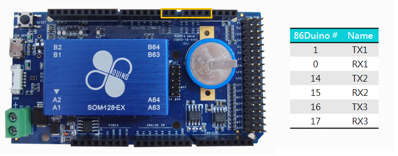
9. TTL UART
There are 3 groups of TTL UART on the 86Duino-One board:
• Tx1 (Pin 1), Rx1 (Pin 0)
• Tx2 (Pin 16), Rx2 (Pin 17)
• Tx3 (Pin 14), Rx3 (Pin 15)
These 3 TTL UART interfaces is capable to communicate at speed up to 6 Mbps. You can use Serial1 ~ Serial3 library to transmit and receive data through these interfaces.
The TTL UART interfaces are accessible on the 86Duino-One header, as shown in the following figure:
The TTL UART interfaces on 86Duino-One is able to support both Full-duplex and Half-duplex mode, and able to directly communicate with the Robotis Dymanixel AX-12+ servo, which has an UART interface in Half-duplex mode.
In an 86Duino sketch (program), you can use the begin() function, within the Serial1 ~ Serial3 library to set the interface to function in Half-duplex mode.
Note: The output signal for the 3 TTL UART interfaces are LVTTL (0 ~ 3.3V). Do not directly connect RS-232 device to these TTL UART. The 12V signal from RS-232 device cause permenant damage.
Unlike the Arduino and Raspberry Pi platforms, which require external circuitry added to support Half-duplex communication, as indicated in the following URL.
TTL UART wiring example
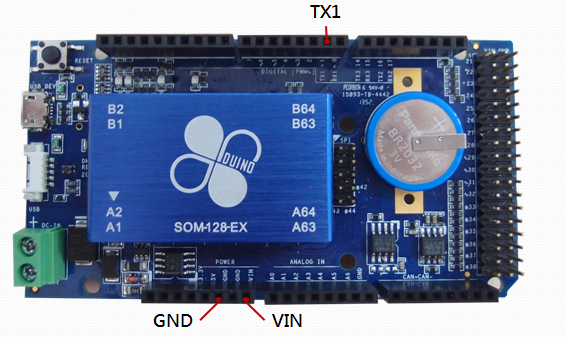
For this example, we will connect a Robotis Dymanixel AX-12+ servo to the 86Duino-One board, as shown in the following figure:
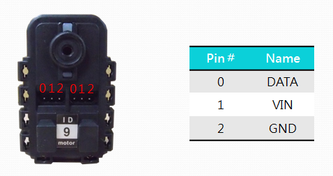
To support the Dymanial AX-12+ servo, with a Half-duplex UART interface, UART on the 86Duino-One must be configured to function in Half-duplex mode. In Half-duplex mode, the UART’s Tx pin is used to transmit and receive data and the Rx pin is not used. The Data pin from the AX-12+ servo is connected to the Tx1 (Pin 1) on the 86Duino-One, Vin and GND pins from AX-12+ are connected to Vin and GND on the 86Duino-One, as shown in the following figure:
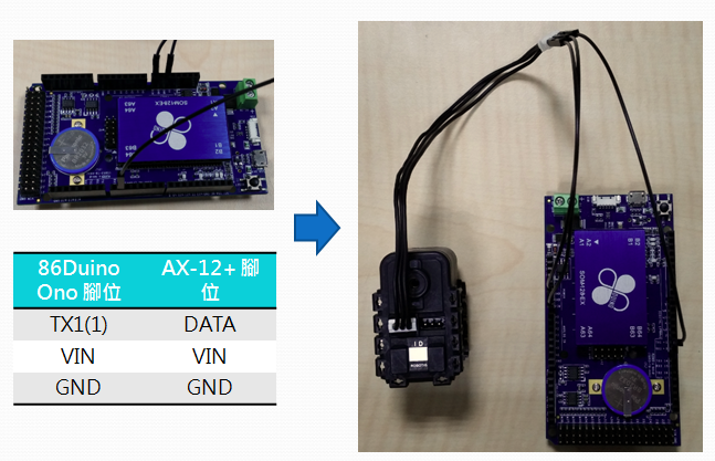
With the AX-12+ servo connected to 86Duino-One as above, you can use Serial1 library in the 86Duino sketch to communicate with AX-12+. In addition, you need to configure the 86Duino-One to communicate at the same BAUD RATE as the AX-12+ servo, and supply sufficient Vin voltage (7V ~ 10V) in order for the AX-12+ servo to function.
10. RS-485 serial port
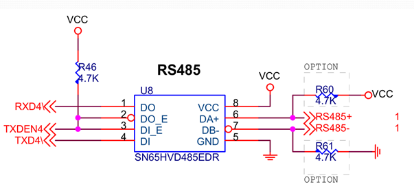
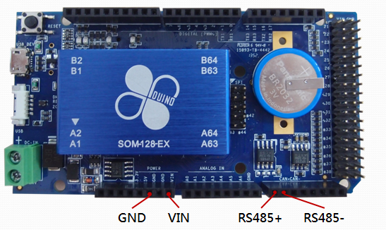
There is one RS-485 interface on the 86Duino-One board, which can support communication speed up to 6 Mbps. Use the Serial485 library to transmit and receive data. The RS-485 interface is accessible on one of the header, as shown in the following figure:
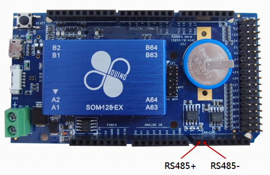
Note: The RS-485 interface uses differential signal, different from the TTL UART and not compatible to communicate with TTL UART.
RS-485 wiring example
For this wiring example, we will connect a Dymanixel RX-28 servo with RS-485 interface to the 86Duino-One board, as shown in the following figure:
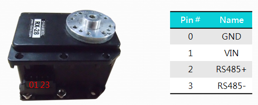
Connecting the Dymanixel RX-28 servo’s RS-485, Vin and GND pins to the 86Duino-One board, as shown in the following figures. Within an 86Duino sketch, use the Serial485 library to communicate with the servo.
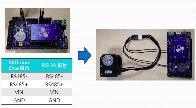
Note: The BAUD RATE for both the 86Duino-One and RX-28 servo must be configured to the same setting in order to communicate. In addition, Vin requires sufficient voltage (12V ~ 16V) to support the RX-28 servo.
11. CAN Bus interface
CAN Bus is a serial bus protocol. It’s a highly reliable communication interface initially designed for the automotive industry and now widely adopted in the industrial automation industry. For more information about CAN bus, visit the following Wikipedia page.
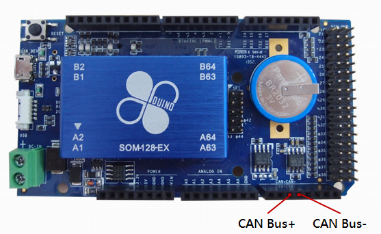
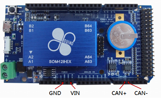
There is one CAN Bus interface on the 86Duino-One board, as shown in the following figure:
From the 86Duino Coding environment, you can use the CANBus library to communicate via the CAN Bus interface.
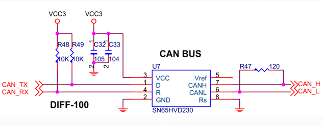
Different from the CAN Bus on the Arduino Due, which requires external transceiver circuitry in order to communicate with a CAN Bus device, the TI SN65HVD230 transceiver chip is built-in as part of the CAN Bus circuitry on the 86Duino-One board, enabling the 86Duino-One to be able to connect directly to external CAN Bus device, as shown in the following figure.
Note: Since the CAN Bus interface on the Arduino Due does not have a transceiver, it cannot be directly connected to the 86Duino-One board.
CAN Bus interface wiring example
For this example, use the CAN232 adapter from LAWICELAB, as shown in the following figure:
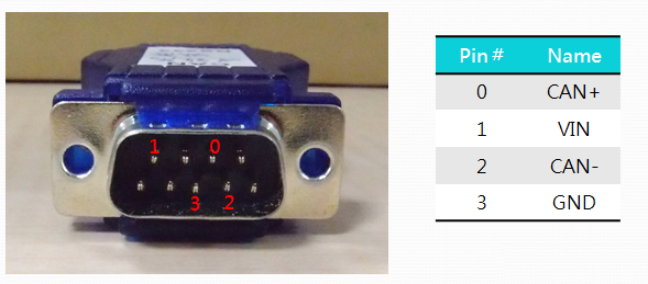
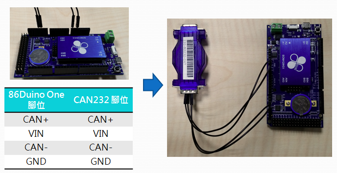
The CAN232 adapter requires 6V ~ 15V power source to function, which can be supplied through Vin. To communicate with the CAN232 adapter, cnnect the CAN+, CAN-, Vin and GND pins from the CAN232 adapter to the 86Duino-One board, as shown in the following figure:
12. SPI interface
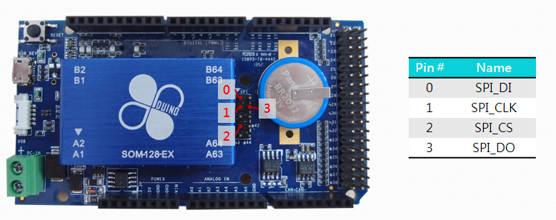
The 86Duino-One board has one SPI interface, compatible to Arduino Leonardo and Arduino Due, and include the CS pin, as shown in the following figure:
From the 86Duino Coding environment, you can use the SPI library to interact with the SPI interface.
13. LAN interface
There is one 10/100 Mbps LAN interface on the 86Duino-One board. You can use the Ethernet library to transmit and receive through the LAN interface. The LAN interface is accessible via a 4 pins micro connector on the edge of the PCB, as shown in the following figure:
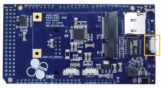
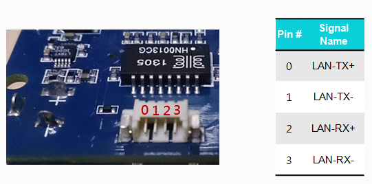
The LAN interface routed through a 1.25 mm pitch 4-pin micro connector. The micro connector for LAN interface is designed to support robotics application. An adapter cable converting this connector to an RJ45 jack is needed to support the common RJ45 networking cable. The 86Duino-One cable kit includes an adapter cable that convert the 4-pin micro connector LAN interface to an RJ45 jack. For more information about the cable kit, visit the following URL.
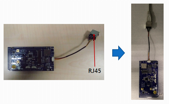
LAN interface wiring example
To provide an RJ45 jack to support the common RJ45 networking cable, the 4-pin micro connector to RJ45 jack adapter cable, from the 86Duino-One cable kit, is used, as shown in the following figure:
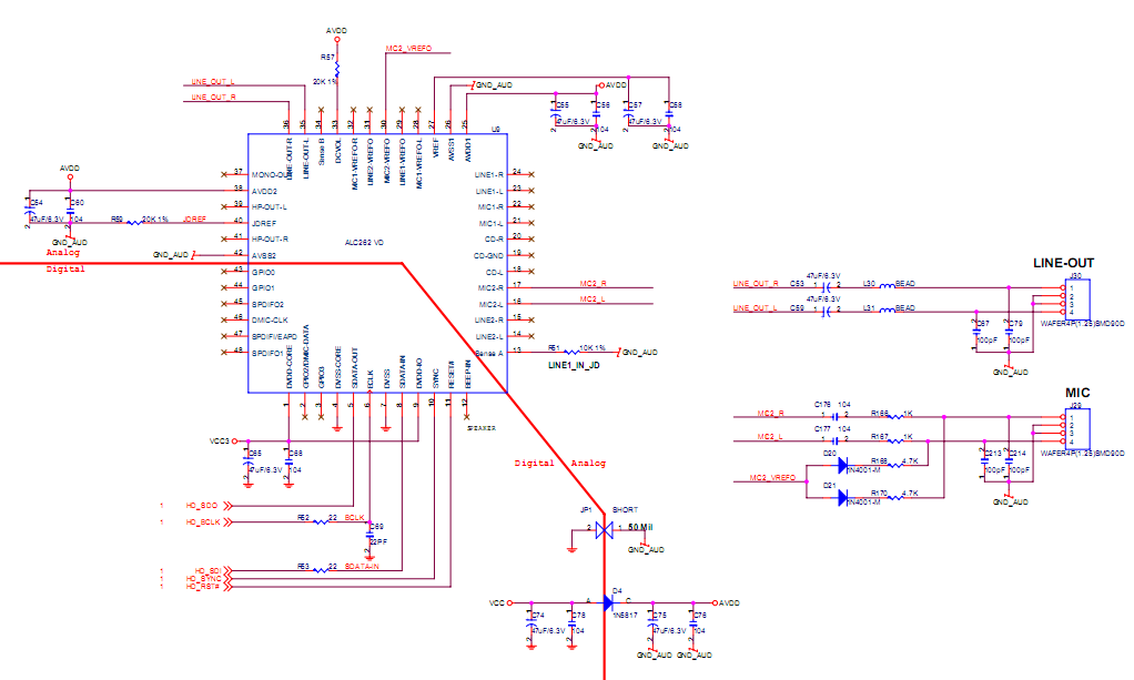
14. Audio interface
The 86Duino-One is built with HD audio with a Realtek ALC262 HD audio Codec chip. There is a stereo output and a microphone input accessible on the 86Duino-One board, as shown in the following schematic.
From the 86Duino Coding environment, you can use the audio library to interact with the audio interface.
The Realtek ALC262 Codec chip is located on the back side of the 86Duino-One board, as shown in the following figure:
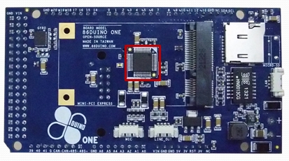
Stereo output and microphone input are accessible via two 4-pin micro connector below the Realtek ALC262 chip.
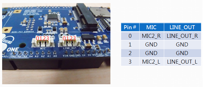
There are two 1.25 mm pitch 4-pin micro connector, below the Realtek ALC262 chip, for stereo output (LINE_OUT) and microphone input (MIC), as shown in the following figure:
To connect headphone, audio amplifier or microphone to the 86Duino-One board, you need to use 3.5 mm TRS adapter cable.
Audio interface wiring example
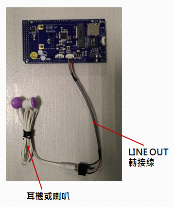
For this example, a headphone with 3.5 mm plug is connected to the 86Duino-One stereo output (LINE_OUT) through an 3.5MM TRS adapter cable, which is included in the 86Duino-One cable kit, as shown in the following figure:
15. USB 2.0 host interface
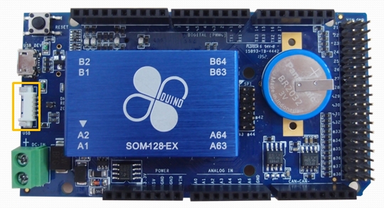
There is one USB 2.0 Host interface on the 86Duino-One board, which can support USB keyboard and mouse. From the 86Duino Coding environment, you can use the USB Host library to interact with attached USB keyboard and mouse. When using Windows or Linux operating system with 86Duino-One board, the USB 2.0 host interface also support USB WiFi module and USB camera. The USB 2.0 host interface is accessible through a micro connector, as shown in the following figure:
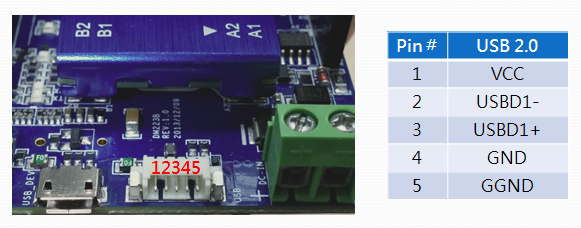
The USB interface is accessible via a 1.25 mm pitch 5-pin micro connector. You can use an adapter cable to convert 5-pin micro connector to USB Type A connect, which is included as part of the 86Duino-One cable kit. The 5-pin micro connector for the USB interface is a design consideration for robotics application to minimize the size of the PCB, by not having the USB Type A connector onboard. In addition, using an adapter cable, the USB interface can be easily extended onto the chassis or enclosure to be accessible externally.
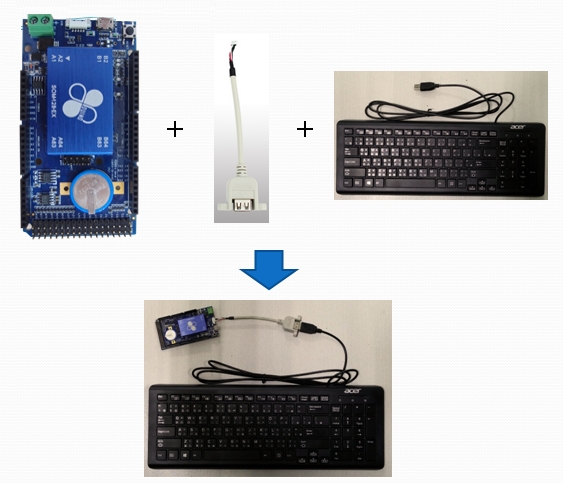
USB 2.0 host interface wiring example
Using the USB Type A adapter cable available as part of the 86Duino-One cable kit, you can attach an USB-keyboard to the 86Duino-One board, as shown in the following figure:
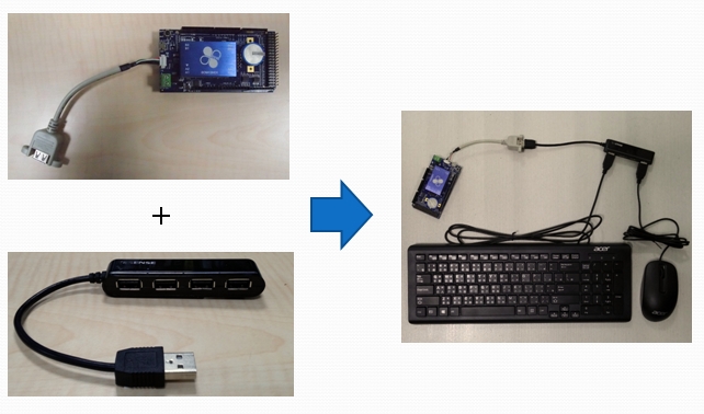
To connect multiple USB devices to the 86Duino-One board, use an USB hub, as shown in the following figure, to support an USB-keyboard and USB-mouse:
16. Encoder interface
There are 4 group of Encoder interfaces on the 86Duino-One, each has three pins, A, B and Z, as shown in the following figure:
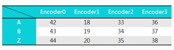
The Encoder interfaces on the 86Duino-One board support optical incremental encoder and SSI absolute encoder. From the 86Duino Coding environment, you can use the Encoder library to read encoder value. The maximum input signal frequency for the each encoder interface is 25 MHz.
Encoder interface wiring example
Using an AM4096 rotary encoder chip as example, the following figure shows the pins out for an AM4096 module:
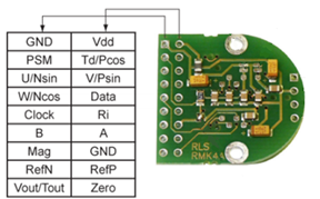
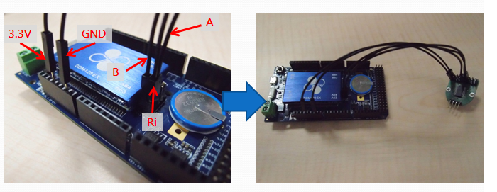
In the above figure, there is a group of A/B Phase incremental encoder signal output, where the pins marked as A, B and Ri. The A/B Phase incremental encoder is connected to the 86Duino-One, where A, B and Ri, along with Vdd and GND pins are used, as shown in the following figure (Vdd is connected to 3.3V output on the 86Duino-One):
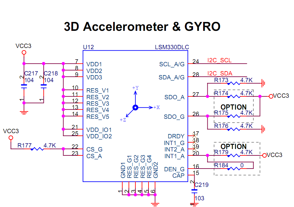
17. Three Axis Accelerometer and three axis
The 86Duino-One board is built with an LSM330DLC chip, which provide 3 axis accelerometer and 3 axis gyro sensor to support robotics application, as shown in the following schematic. From the 86Duino Coding environment, you can use the FreeIMU1 library to access the accelerometer and gyro sensors.
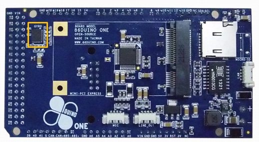
The LSM330DLC chip is located near the top left corner of the PCB in the following figure:
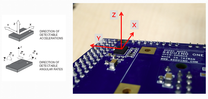
The X, Y and Z orientation for the LSM330DLC chip is shown in the following figure:
Note: The MSM330DLC chip is connected to the 86Duino-One’s I2C interface, using the 0x18 and 0x6A address (these are 7-bit address where the corresponding 8-bit address are 0x30 and 0xD4). Avoid using these addresses for other attached I2C device.
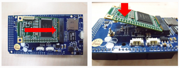
18. Mini PCI-E interface
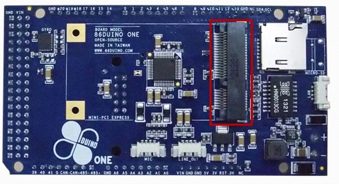
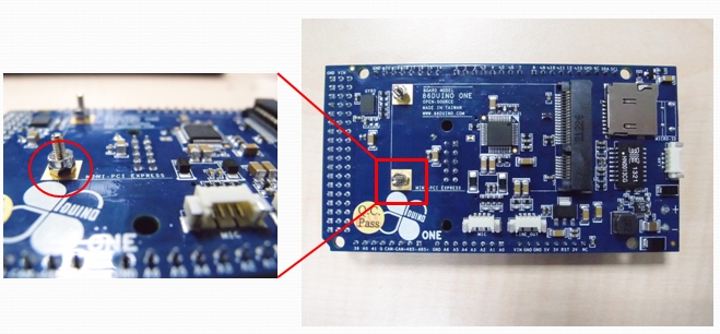
The 86Duino-One board has one Mini PCI-E slot on the back side, as shown in the following figure (marked in red). The Mini PCI-E slot is an expansion slot that can support VGA and WiFi card.
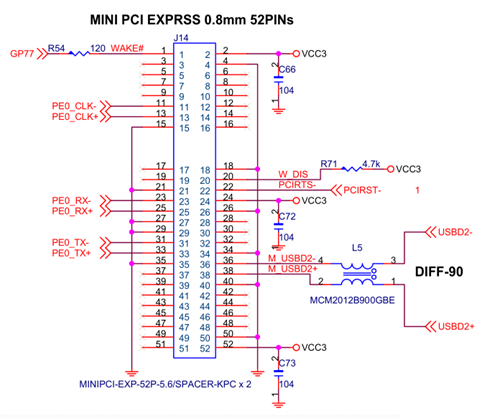
Schematic for the Mini PCI-E slot:
Mini PCI-E interface usage example
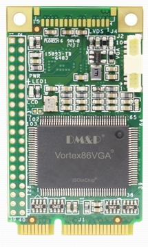
The Vortex86VGA display card, a Mini PCIe VGA card, is used for this example, as shown in the following figure:
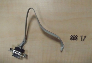
Accessory package for the Vortex86VGA display card includes a VGA adapter cable, 2 screws and 6 nuts to secure the card, as shown in the following figure:
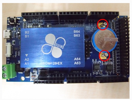
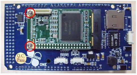
To install the Vortex86VGA card onto the 86Duino-One board, insert the two screws through the two holes next to the CMOS battery, as shown in the following figure:
Flip over the 86Duino-One board and use two nuts to secure screw, as shown in the following figure:
Next, insert the display card with the Vortex86VGA chip on top into the Mini PCI-E slot, as shown in the following figure (Make sure the card is fully inserted to avoid poor contact):
Use the remaining two nuts to secure the display card, as shown in the following figure:
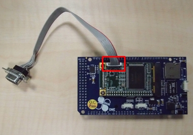
Insert the VGA adapter cable to the connector, as shown in the following figure:
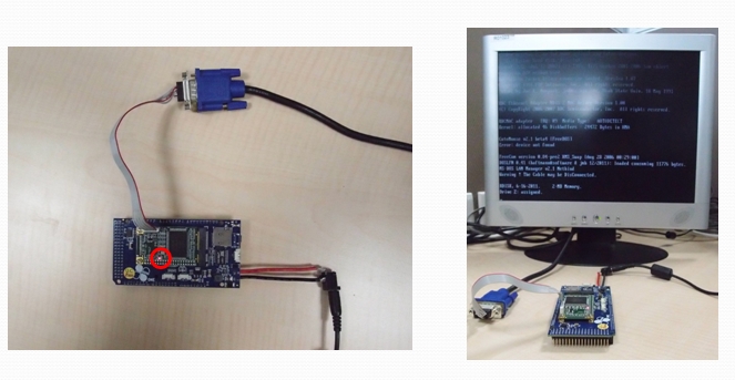
Finally, connect a VGA monitor to the VGA connector and turn on power to the 86Duino-One board. After power is applied, the red LED on the Vortex86VGA display card will turn on and the monitor should have display showing startup activities, as shown in the following figure:
Note: With the Vortex86VGA display card added, the required power is increased to 600mA @ 5V, which is higher than the 500mA current available through an USB 2.0 host interface. You need to use alternative 5V power source that can provide sufficient current at 5V needed to power the board.
19. CMOS battery
It’s a common design practice to use a small coin battery to maintain BIOS settings, saved to complementary metal-oxide-semiconductor (CMOS) SRAM, which also function as the power source for the RTC chip. The CMOS battery’s primary function is to maintain BIOS settings and keep the RTC (real time clock) running during power off.
The 86Duino-One board is based on the x86 CPU architecture and is designed with a CMOS battery, as shown in the following figure:
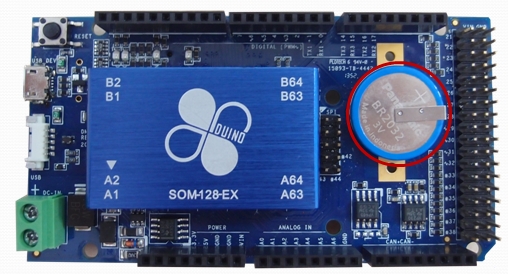
For the 86Duino-One board, the CMOS battery is used to maintain real-time-clock and EEPROM library store in the CMOS, and is not used to maintain BIOS setting. Where there are problem with the CMOS battery, it does not affect the BIOS and the 86Duino-One board is able to boot as expected. However, in the event when the CMOS battery has problem, the RTC (real time clock) will not continue to run and the EEPROM library stored in the CMOS will be lost. To prevent losing EEPROM library stored in the CMOS and maintain accurate real time clock, avoid shorting the CMOS battery.
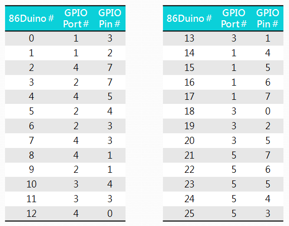
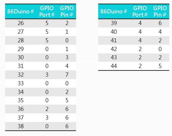
Appendix 1: 86Duino-One Pin Definition and Corresponding Vortex86EX GPIO Ports
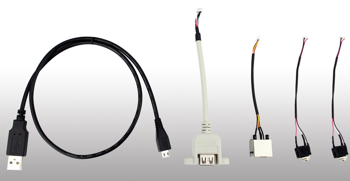
Appendix 2: 86Duino-One Cable Kit
The 86Duino-One cable kit includes: Micro-USB cable, USB host interface adapter cable, RJ45 Ethernet adapter cable, audio output and microphone input adapter cables, as shown in the following figure:
Appendix 2: 86Duino One Open-source hardware
The text of the 86Duino reference is licensed under a Creative Commons Attribution-ShareAlike 3.0 License. Code samples in the reference are released into the public domain.